Tube info online
Hi Fragman
I have an outline of online diy tube materials if you are learning. Happy to send you a copy but I cannot email you through diyaudio. Drop me an email if you want it. You might find it helpful. You have been given a number of good sites above for learning. wryder@chartermi.net
Hi Fragman
I have an outline of online diy tube materials if you are learning. Happy to send you a copy but I cannot email you through diyaudio. Drop me an email if you want it. You might find it helpful. You have been given a number of good sites above for learning. wryder@chartermi.net
Frank,
Thank you for the kind words in this and the other post. I'm not really all that knowledgable, but I enjoy helping as a mark of respect for all the people who've helped me. I think I also miss instructing.
Rick,
How are you going with the design? Is it making sense? Let me know when you want to push on with the driver stage and power supply.
Sorry if you've been waiting for me but I still haven't recovered my data from the HDD crash.
Cheers
Brett
HD CRASH
Brett,
Could it be that the disk was upset by the amount of inverse peak rubbish them diodes were throwing back in the mains?😀
You deserved the compliment,didn't you?😉
Cheers,🙂
Brett,
Could it be that the disk was upset by the amount of inverse peak rubbish them diodes were throwing back in the mains?😀
You deserved the compliment,didn't you?😉
Cheers,🙂
300b
Hi Brett,
I don't know if I'll ever be ready to move on to either the driver or power supply as you'll see from my questions.
I did read Bench's literature as well as an old text Electronics for Scientists by Malmstadt, Enke and Toren, W. A. Benjamin, Inc. 1963. I plotted a loadline using the 350V and 60ma at the plate. I suppose this is a quiescent point for this tube.
Not sure what this means "Vg (Ec) = -74V so Vp = 424V". -74V is the zero signal voltage at the grid? Grid voltage will swing around this point?
424V?
Let's see if I understand anything yet.
With 350V at the plate and 5VAC or DC on the filament, 60 ma of current will flow across the 300b tube? These values will set the RL (load resistor) value? For the Rk (cathode resistor), use 5 V, 60 ma? Where does the grid bias discussion come in? -74V signal voltage fits in somewhere?
If grid stays there, 60 ma goes across tube? Grid goes to 0V, then ip=about 95ma depending on load line plot. And, grid goes to over -140 or so then cut-off reached?
If 74V is op point for grid, then must have driver stage between a CD player (2VAC), for example, and output tube?
Pretty confused,
Rick
Load resistor controls the current through the tube; keeps the power down (21W vs 36W max) assuming a Eb constant value (say 350V)?
Cathode resistor controls the grid bias voltage? Choose a bias voltage from the characteristic graph and calculate Rk based on i? I think the literature suggests using ib.
So, here's the stupid question on self-bias: if the above is correct, then how does ib flow from cathode to grid? Does any i flow between cathode (filament) and grid?
rick
Rick,
I'll answer your last two posts in this one. I've been delaying it because I hoped to have some drawings to post as well. I might just draw them in .wobblyhand format and scan.
<b>Not sure what this means "Vg (Ec) = -74V so Vp = 424V". -74V is the zero signal voltage at the grid? Grid voltage will swing around this point?
424V?</b>
In the datasheets when they talk about plate voltage (Vp), you can usually assume they mean the voltage between the plate and cathode, as the measurements are usually done with the cathode grounded, and the negative bias applied as a voltage directly to the grid. For reference, this is called fixed bias.
So the op point I mentioned the other night from the WE datasheet with Vp=350V, means that's the voltage between plate and cathode (Vp-k). Now, as we're going to use cathode bias, there is a resistor between the cathode and ground. With a quiescent of 60mA flowing through the tube, and no signal on the grid, the voltage drop across this resistor is going to be 74V. This way the grid is at 0V, and the cathode +74V (wrt ground), so we have the same effective situation as if the cathode was grounded directly, and the -74V was applied through a power supply. The "control" signal for a tube is the relative difference in voltage between the grid and cathode.
With the cathode sitting at +74V above ground, and there being 350V across the tube, if we measured the voltage on the plate, we would see, 350 + 74 = 424V between the plate and ground.
All the current from the power supply travels through the transformer primary. Using a Hammond 1627SE as an example, it has 280 ohm DC resistance.
Given V=IR, 0.06 x 280 = 16.8V
Add this to the 424V we already have, and voila, the power supply will need to be 424 + 16.8 = 441V
The maximum signal that can be applied to the grid, is theoretically 74V peak, before grid current will flow. Grid current flows when the signal voltage is greater than the bias. Most tubes are happy with a slightly excess signal, occaisionally, and some big transmitter tubes won't actually produce much poer unless you drive the grid positive <i>a lot</i>, but that's another sujlect. Most often having a positive grid bias is called Class A2 or AB2.
<b>With 350V at the plate and 5VAC or DC on the filament, 60 ma of current will flow across the 300b tube? These values will set the RL (load resistor) value? For the Rk (cathode resistor), use 5 V, 60 ma? Where does the grid bias discussion come in? -74V signal voltage fits in somewhere?</b>
The first sentence I answered above, except that the 5V filament voltage is required to heat the tube, ie provide a source of electrons for it to operate.
RL is determined by a number of things, but a general rule of thumb is 3-4 x the plate resistance of the tube. For the operating point we're using, WE have conveniently supplied it for us on p2 of the datasheet, RH column. Rp, or the internal resistance of the tube, in this case, at this operating point is 780 ohms so a transformer with a Zp (or RL) = 3000R is 3.85 x the Rp. The chart on the bottom of p5 shows a graph of the relationship between RL, power output and distortion for the chosen operating point, conveniently ours too. The distortion is the amount ptoduced at full power, and drops linearly with signal level, so the number isn't as bad as it looks. Most musical signals are at least 20dB below clipping, or well under a watt in this case, so the average THD will be under 0.3% or so.
Rk: That's easy to calculate. V=IR, so R=V/I = 74/0.06 = 1233 ohms, 1200 is close enough.
<b>If grid stays there, 60 ma goes across tube? Grid goes to 0V, then ip=about 95ma depending on load line plot. And, grid goes to over -140 or so then cut-off reached?</b>
Yep. Once a load line is plotted on the graph, you can simply read what the plate voltage, plate current and grid voltage are at any point.
<b>If 74V is op point for grid, then must have driver stage between a CD player (2VAC), for example, and output tube?</b>
Yep again. A CDP if it's to standard will put out 2Vrms at maximum modulation, or 2.8Vpk. So to clip the 300B, we need to design a driver that can take that and amplify it to 74Vpk, or give us about 26x (28dB) voltage gain. The driver also needs to be able to provide enough current to the grid of the 300B to slew it quickly enough to get a good high frequency response. More on this later. It's also better that the driver is able to swing more than the required grid voltage, so that the whole amp doesn't clip at once (sounds much worse) and to give some flexibility to change the bias later. Remember we're running conservatively.
<b>Load resistor controls the current through the tube; keeps the power down (21W vs 36W max) assuming a Eb constant value (say 350V)?</b>
I wouldn't look at it quite this way.
The current that flows through the tube is controlled by the grid-to-cathode voltage and it's transconductance. Transconsuctance is the amount of change in current, brought about by a certain change in grid to cathode voltage. The tube's filament type and temperature and internal structure determine both the transconductance and the Rp for a given tube.
Tube dissipation is from the combination of Vpk and Ip. P=VI = 350 x 0.06 = 21W. The bias point chosen is a juggling of Vpk, Ip, power and distortion levels and the tube specification. The load is chosen juggling all of these to get the max voltage and current swings (hence max power) as well as staying in the most linear part of the curves (lowest distortion) and within the max dissipation of the tube. A smaller load usually means more power, but more distortion.
<b>Cathode resistor controls the grid bias voltage? Choose a bias voltage from the characteristic graph and calculate Rk based on i? I think the literature suggests using ib.</b>
Yep. Did that above.
<b>So, here's the stupid question on self-bias: if the above is correct, then how does ib flow from cathode to grid? Does any i flow between cathode (filament) and grid?</b>
Under most circumstances no current flows from the cathode to the grid. All the current flows between the cathode and plate and the grid voltage is like a faucet, letting more or less electrons through as you turn it more on or off. The cathode boils off electrons, which if the Vgk was zero, would then be able to travel unhindered to the plate. As the Vgk is made more negative, it more readily repels the electrons (like charges repel) until at a certain point no more will flow, ie cutoff.
You were pretty close with most of it. I hope it makes more sense now.
I'll try to draw up some sketches and curves with RL etc, and some for the driver too for next week.
Cheers
Brett
300b characteristics
A few clarifications please,
WE's sheet shows:
Typical Operating Conditions and Characteristics
Single Tube Amplifier--Class A1
Plate Voltage...........350 Volts
Zero Signal Plate Current .......60 ma
Is this the operating point, ie quiescent point? no signal state? If so, the plate voltage should not increase from this point since the max plate voltage is specified as 400V?
Do I use the value of 77 ma (given as Maximum Signal Plate Current) as the 0V, max i Load line end? Use 350V at 60 ma as operating point and connect these points for the load line?
So, my understanding at this point is: with the grid at 74 V less than the cathode (using a common cathode design), quiescent point is 350V at 60 ma flowing, a signal comes in causing the grid voltage to increase from -74V to a max of 0V alway staying negative wrt cathode. No signal then plate returns to 350V and 60 ma?
-74V is the self-bias assuming that I design the cathode resistor correctly and have the plate at 350V and 60ma quiescent?
For gain then, an change of Vc=74V yields a change of Vp=350-73V=287V? So, 277/74=3.74 (3.9 given on sheet).
I assume that the tube will not go above 350V and less than 60ma since this is the quiescent point? An incoming signal change the operating point to go further to the left on the loadline?
Question: when drawing the loadline, assume the voltage drop across RL=0 then Vb=Vout? Therefore, one point on loadline is 350V, 0ma. The other end of loadline is assuming Vp=0 and plate current =77ma since voltage drop across RL=350V. But this line does not include the quiescent point (350,60 ma)?
I will try to include a schematic and load line on next post to illustrate the question.
Thanks for your assistance,
Rick
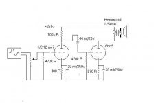
As part of the learning process, I thought it best to design and build a simple SE 6bq5 amp that may become a part of the 300b amp. I breadboarded this amp using DC power supplies for testing. It amplified the CD player.
I make no representation that I know what I am doing here. Perhaps with your review, comment and testing, I will learn a bit more. I need help with the capacitor selection, grid leak resister choice, OPT hook up, etc.
Your thoughts and guidance is greatly appreciated,
Thanks,
Rick
I make no representation that I know what I am doing here. Perhaps with your review, comment and testing, I will learn a bit more. I need help with the capacitor selection, grid leak resister choice, OPT hook up, etc.
Your thoughts and guidance is greatly appreciated,
Thanks,
Rick
Attachments
I'll try again
Let's see if this file will attach...
I have 2 Hammond OT 1627's also for my 300b when I think that I am ready. I could use them instead of the 125ese's.
I hooked something like this up on my tabletop with a pwr supply that was current limited. (I think the supply was limited to 5 ma?? Does that sound right?)
It played! But, really awful sound! I used some decade boxes for the load resistor and switched it around just for kicks...not much better.
Bought a Hammond power trans (215v, 269 ma)...hooked it up with bridge rectifier and sprague cap (200, 200v). Bad hum. Bad sound.
Just wondering and trying to learn, I truly hope this image works,
Rick
Attachments
Re: I'll try again
5 ma ain't close to enough if it's supplying the EL84 triode connected as you show and the 12AX7. You probably need more like 30ma or 40ma. If it indeed current limits the B+ at 5 ma, I'd expect this is why it sounds bad.
What are you doing with the EL84 screen connection? Tying it to the plate I hope.
Check and make sure your coupling cap is rated higher than 25V as shown in your schematic. More like 200V is what I would expect, the plate of your 12AX7 is going to be around 100V isn't it?
You need far more filtering than one cap coming off your bridge rectifier. That's why it's humming. Try adding a 100 ohm 20 Watt resistor in series with the B+ after the cap and then another cap after that (bigger than 200V please, more like 300V - same for the bridge rectifier.) The 215V power trans will give *way* more than 200V when hooked up full wave bridge. I'm suprised your filter cap didn't flame out.
fragman56 said:I hooked something like this up on my tabletop with a pwr supply that was current limited. (I think the supply was limited to 5 ma?? Does that sound right?)
It played! But, really awful sound! I used some decade boxes for the load resistor and switched it around just for kicks...not much better.
Bought a Hammond power trans (215v, 269 ma)...hooked it up with bridge rectifier and sprague cap (200, 200v). Bad hum. Bad sound.
Rick
5 ma ain't close to enough if it's supplying the EL84 triode connected as you show and the 12AX7. You probably need more like 30ma or 40ma. If it indeed current limits the B+ at 5 ma, I'd expect this is why it sounds bad.
What are you doing with the EL84 screen connection? Tying it to the plate I hope.
Check and make sure your coupling cap is rated higher than 25V as shown in your schematic. More like 200V is what I would expect, the plate of your 12AX7 is going to be around 100V isn't it?
You need far more filtering than one cap coming off your bridge rectifier. That's why it's humming. Try adding a 100 ohm 20 Watt resistor in series with the B+ after the cap and then another cap after that (bigger than 200V please, more like 300V - same for the bridge rectifier.) The 215V power trans will give *way* more than 200V when hooked up full wave bridge. I'm suprised your filter cap didn't flame out.
Re: I'll try again
One thing further, current limiting is not something you want in a B+ supply. You want the B+ to supply whatever current the tubes ask for.
Hope this helps!
Jeff
fragman56 said:I hooked something like this up on my tabletop with a pwr supply that was current limited. (I think the supply was limited to 5 ma?? Does that sound right?)
Rick
One thing further, current limiting is not something you want in a B+ supply. You want the B+ to supply whatever current the tubes ask for.
Hope this helps!
Jeff
Thank you
Jeff,
Thank you for your advice!
I have the output tube hooked up triode style, I think. (Tied to the plate).
The Hammond pwer transformer says it will put out 215V but I measure much more with my Fluke meter...over 300VDC?? Probably has something to do with rms and peak....
Looks like I need to select components more carefully wrt voltage!!!
I will hook up the resistors-and-cap filter system as you suggest and give it a shot.
Cathode resistors ok with that supply?
Should I put in the Hammond 1627's instead of the 125ese's?
Bypass caps ok I presume since no comment there. Shouldn't I use as big a bypass cap that I can find because Xc should be minimized for low hz (say 50)? How does this thinking relate to the coupling cap? Large coupling cap?
Can't wait to try your suggestions!
Thanks again,
Rick
Re: Thank you
Sort of, it really has to do with AC and DC. The power transformer is rated in AC volts which is typically measured in RMS Volts. Your rectifier and smoothing caps convert this to DC.
Yes!!!! Unless you enjoy the smell of smoke.
Have a look here:
http://www.audioxpress.com/resource/audioclass/
The last three articles talk about power supplies.
Dunno, they look reasonable, but that doesn't mean they aren't pulling too much current from the tubes. I haven't got the time to do the calculations for you. The other articles on the page listed above talk about designing amp stages.
I have no opinion on this.
There are rules of thumb here. I don't have time to explain them, though. I think those articles explain the cathode bypass cap calculation. Your caps are all plenty big enough. Bigger caps extend the low bass, but big caps tend not to sound as good as small ones. In particular, I'd try a .05 or .1 uF coupling cap.
I know you want to build stuff now, but you really need to read, read and then read some more.
fragman56 said:The Hammond pwer transformer says it will put out 215V but I measure much more with my Fluke meter...over 300VDC?? Probably has something to do with rms and peak....
Sort of, it really has to do with AC and DC. The power transformer is rated in AC volts which is typically measured in RMS Volts. Your rectifier and smoothing caps convert this to DC.
Looks like I need to select components more carefully wrt voltage!!!
Yes!!!! Unless you enjoy the smell of smoke.
I will hook up the resistors-and-cap filter system as you suggest and give it a shot.
Have a look here:
http://www.audioxpress.com/resource/audioclass/
The last three articles talk about power supplies.
Cathode resistors ok with that supply?
Dunno, they look reasonable, but that doesn't mean they aren't pulling too much current from the tubes. I haven't got the time to do the calculations for you. The other articles on the page listed above talk about designing amp stages.
Should I put in the Hammond 1627's instead of the 125ese's
I have no opinion on this.
Bypass caps ok I presume since no comment there. Shouldn't I use as big a bypass cap that I can find because Xc should be minimized for low hz (say 50)? How does this thinking relate to the coupling cap? Large coupling cap?
There are rules of thumb here. I don't have time to explain them, though. I think those articles explain the cathode bypass cap calculation. Your caps are all plenty big enough. Bigger caps extend the low bass, but big caps tend not to sound as good as small ones. In particular, I'd try a .05 or .1 uF coupling cap.
I know you want to build stuff now, but you really need to read, read and then read some more.
Re: I'll try again
Hi Rick,
I pretty much agree with what Jeffs posted above.
Working from the output to the input.
Output stage: The EL84 will be pulling about 35mA at idle. What you have looks like it's straight off the datasheet. The 125ese is a 'universal' trans I think so roughly 3k5 would be a good place to start for the load impedance, as per the datasheet.
The EL84 cathode bypass needs a rating of 25V, but I'd go with a standard 35V for a bit of safety. To give a 10Hz corner frequency, the bypass needs to be about 125uF for 10Hz. Scale for other corner frequencies. With the value of 20uF you have the -3dB point will be 62Hz.
Output is good for nearly 2W at 8% THD, almost entirely second harmonic.
Interstage: The R and C form a high pass filter. With the values you have f= 0.77Hz. Quite low enough. The rating on the cap should be greater than the B+, so a minimum of 300V, and 400V versions wouldn't be a bad idea. The 470K is a satisfctory value for the grid resistor.
Driver: Just reading the datasheets, Rk should be 1k5, so Ia will be 0.68mA. Calculated gain will be about 60. Bypass cap should be 20uF/35V for the same 10Hz as before. I'm not telling you to use these values, but they will help you scale the value simply: more capacitance = lower frequency.
The EL84 needs 9.5V peak before it clips. The driver stage has a gain of 60, so the amp will clip with 0.16Vpeak at the input. This is too much gain, so you'll need that attenuator at the input. A standard CDP puts out 2Vrms (2.8Vpeak), so for full power this amp only needs a driver with a gain of 9.5/2.8 = 3.4.
I didn't include all the maths, but I can ad it in later if you'd like. Or you can read all about it here.
http://www.aikenamps.com/CommonCathode.htm
The 12AX7 example used is the same as your op points.
<b>I have 2 Hammond OT 1627's also for my 300b when I think that I am ready. I could use them instead of the 125ese's.</b>
No, the 1627 has an impedance of 2k5 which is a bit low for the EL84 in SE. Power will go up a bit, as will distortion if you use them and it already has enough 2H as it is.
<b>I hooked something like this up on my tabletop with a pwr supply that was current limited. (I think the supply was limited to 5 ma?? Does that sound right?)</b>
No that's way too low. The EL84 is drawing 35mA at idle, and the 12AX7 0.7mA. At the onset of clipping, the amp will need about double this.
<b>It played! But, really awful sound! I used some decade boxes for the load resistor and switched it around just for kicks...not much better. </b>
I'm not surprised at either.
<b>Bought a Hammond power trans (215v, 269 ma)...hooked it up with bridge rectifier and sprague cap (200, 200v). Bad hum. Bad sound.</b>
I'm surprised the cap lived at all. It needs to be about double that voltage rating.
I'll add another post later tonight to breifly explain how to calculate power supplies. Earlier in this thread I mention PSUD2 which is a free simulator for power supplies that will be worth getting and playing with to help visualise all this.
Cheers
I checked the setup today; the filter cap was rated at 250V--as you say still too little.
Put in the pi section RC using 100 ohm at 12 watts (all I had lying around) and two caps (600 V, 10 mf and 40 mf). Changed the coupling cap to .1, 100 volts.
Still bad hum and the output at unity is very low. Perhaps bad rectifier for the hum. No idea why the low volume at the speaker.
Next step: Check/change bridge rectifier. check caps with cap meter. Troubleshoot with ocilliscope. Disassemble and start over using all new components.
Your suggestions welcome,
Thanks,
Rick
Hi Rick,
For two channels, I'd also prefer the 50uF you heve there now to be doubled.
Also; - replace the first PSU cap and the coupling cap. FIRST!
- check polarity on all the caps. Some cap types like electrolytics are polarised, ie they go in one way around. The +ve terminal should be at the PSU for the power supply caps with the negatives at the earth. The cathode bypass caps should have the +ve to the cathode end, -ve to earth. The coupling cap should have the +ve to the plate of the 12AX7 and the -ve to the grid of the EL84.
- tightly twist each of the heater wires together for each tube, keep them away from the signal wiring as much as possible, and if they must cross, do it at 90*.
- check all your wiring and connections to make sure there are no mistakes. Same with solder joints for bad/cold joints.
Finally, don't get too frustrated or put off at this stage. You're on a very steep part of the learning curve and problems and mistakes are inevitable. Once you ge through it sucessfully, the SE300B will be a lot easier from the lessons learned, and subsequent amps easier still.
Keep asking questions.
Cheers
I ran a quick simulation on PSUD2 and the voltage across the first cap is 308V, and the second (in the pi), about 302V. The cap you had in place, if rated at 250V will be toast. You need to replace it with something around 400V.fragman56 said:I checked the setup today; the filter cap was rated at 250V--as you say still too little.
A pi filter never hurts, but if you want 250V instead of the 302V you have now (assuming you replace the first cap in the PSU), you'll need to change the R from 100R to 1k6. If you are powering two channels from the supply, then the R should be 700R.Put in the pi section RC using 100 ohm at 12 watts (all I had lying around) and two caps (600 V, 10 mf and 40 mf).
For two channels, I'd also prefer the 50uF you heve there now to be doubled.
The value of the cap is fine, but the voltage rating is too low. It needs to be the same value as the PSU voltage as a minimum. It might be toast too now.Changed the coupling cap to .1, 100 volts.
Until you have good caps in the PSU and coupler, then it's going to be hard to troubleshootStill bad hum and the output at unity is very low. Perhaps bad rectifier for the hum. No idea why the low volume at the speaker.
Good idea, but try to troubleshoot it before you go so ar as to disassemble the whole circuit.Check/change bridge rectifier. check caps with cap meter. Troubleshoot with ocilliscope. Disassemble and start over using all new components.
Also; - replace the first PSU cap and the coupling cap. FIRST!
- check polarity on all the caps. Some cap types like electrolytics are polarised, ie they go in one way around. The +ve terminal should be at the PSU for the power supply caps with the negatives at the earth. The cathode bypass caps should have the +ve to the cathode end, -ve to earth. The coupling cap should have the +ve to the plate of the 12AX7 and the -ve to the grid of the EL84.
- tightly twist each of the heater wires together for each tube, keep them away from the signal wiring as much as possible, and if they must cross, do it at 90*.
- check all your wiring and connections to make sure there are no mistakes. Same with solder joints for bad/cold joints.
Finally, don't get too frustrated or put off at this stage. You're on a very steep part of the learning curve and problems and mistakes are inevitable. Once you ge through it sucessfully, the SE300B will be a lot easier from the lessons learned, and subsequent amps easier still.
Keep asking questions.
Cheers
Rick,
Read this thread: http://www.diyaudio.com/forums/showthread.php?s=&threadid=8289
I posted a schematic and parts list for my version of the amp you're trying to build. It uses a 5755 as the driver, but a 12AX7 can be sub'd. It works, and sounds great.
Read this thread: http://www.diyaudio.com/forums/showthread.php?s=&threadid=8289
I posted a schematic and parts list for my version of the amp you're trying to build. It uses a 5755 as the driver, but a 12AX7 can be sub'd. It works, and sounds great.
Brett and Joel,
Thanks so much for the feedback!
I just shake my head at the thoughtless things I do. But, the good news--I am learning a bunch!
Brett-
I must become familiar with PSUD. I have probably fried many of the components by now. The tubes are probably ok?
I think that I can scrounge a few more of the large caps. Would paralleling caps at the filter help assuming the proper voltage rating? Parallel caps increases surface area therefore capacity?
I'll have to order a resistor that large. Great advice on joints, connections, 90 degree, etc.--many thanks.
BTW, any comment on the pi config for this amp? I thought about winding an inductor--if I calculated correctly I would need about 5300 feet of wire!?
Joel-
Thanks for the thread site; I saw the schematic and was impressed with its simplicity. Surely I can get this one to work! I may build your version as well.
Was it you that built the 71a ultra-simple, .75 W amp? That one looks fun, too! I may build that one also assuming that I can get through this el 84 and the 300b. I may go for the 71a before 300b.
Happy Holidays to you all, I am blessed,
Rick
- Status
- Not open for further replies.
- Home
- Amplifiers
- Tubes / Valves
- learning, building and testing tube amp