fragman56 said:I just shake my head at the thoughtless things I do. But, the good news--I am learning a bunch!
LOL. We all go through this. I was fortunate enough to have a very learned engineer to look over my shoulder and correct me when I was learning.
PSUD is a very handy tool and so much easier than trying to work it out longhand.Brett- I must become familiar with PSUD. I have probably fried many of the components by now. The tubes are probably ok?
Tubes are very resilient little beasties, and will take all sorts of abuse and keep woking, where a semiconductor would have let the smoke out. Your tubes are probably fine.
Extra capacitance is often a good thing, as it will give lower ripple on the supply rails, and therefore less hum, but certainly don't stress about it. Use Joels circuit as a guide.I think that I can scrounge a few more of the large caps. Would paralleling caps at the filter help assuming the proper voltage rating? Parallel caps increases surface area therefore capacity?
Correctamundo about the increase in surface area. Caps are basically two sheets of conductor, with an insulating dielectric between them, then rolled up and shrinkwrapped or put in a can. Beware voltage rating!
Glad to help. Get that PSU working right first, then step through the circuit again, checking joints, layout etc.I'll have to order a resistor that large. Great advice on joints, connections, 90 degree, etc.--many thanks.
Joel's circuit is very similar to what your's should have been, so maybe just build his. Perhaps he will post or email you a pic of the layout (if he is willing and able) that you can follow to get working, as we know his works well. The power supply is different, so I'll redo it in PSUD tonight and post the details for what parts you have on hand.
Pi is good, though my preference is for chokes.BTW, any comment on the pi config for this amp? I thought about winding an inductor--if I calculated correctly I would need about 5300 feet of wire!?
Wind an inductor? Jeez you're keen. <a href="http://www.tubesandmore.com">AES</a> have a Triad 10H 90mA 270ohm for about $US17. Could you build one cheaper? I haven't calculated a choke in (many) years, so, I dunno about the wire length.
Cheers
Brett said:Perhaps he will post or email you a pic of the layout (if he is willing and able) that you can follow to get working, as we know his works well.
I'd be happy to post the layout I used, if anyone's interested in it.
WIILLING AND ABLE.
Hi,
It won't hurt would it?
Joel,stop looking for that lost post..happened to Brett ,yourself and me too...
See you all in Texas,😀
Hi,
It won't hurt would it?
Joel,stop looking for that lost post..happened to Brett ,yourself and me too...
See you all in Texas,😀
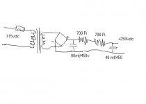
Power supply
Just built and tested the attached PSU as well as revised the circuit as attached.
Hum significantly decreased but still slightly audible (60hz measured). Maybe the wiring config?
I doubled the resistors because I built (on a wooden board) only one channel. Measured voltage was 250vdc on the B+ supply.
Bias measured for Rk output (6bq5) was 8.17 vdc; 1.33 vdc for the 12ax7 Rk--ok, I think.
Sound volume still low. How is output power calculated or measured? This tube should yield about 2 watts out and should have plenty of power for near field listening assuming decent speakers (93 db/1 meter)?
Please excuse the simple questions--and thanks for your help!
Aspiring diyer,
rick
Attachments
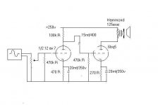
Rick, what is the value of the volume pot at the input?
I ask because you do not need a seperate grid resistor. The volume pot should be from 100k to 1 meg, and takes the place of the grid resistor (470k in your schematic).
I ask because you do not need a seperate grid resistor. The volume pot should be from 100k to 1 meg, and takes the place of the grid resistor (470k in your schematic).
VOLPOTS
Hi Joel,
What is it you have with these volumepots tonight?
Surely a 500K log would be fine,just leave the 470K R out.
Sheez....🙄
Hi Joel,
What is it you have with these volumepots tonight?
Surely a 500K log would be fine,just leave the 470K R out.
Sheez....🙄
Grid Resistor
Hi Joel,
I don't know.
I understood that the 12ax7 needed to be attenuated because it has too much gain for the output tube. I put the grid resistor in because I don't know any better...thanks for your comment. I thought the grid resistor is for bleeding off ???? Perhaps you can explain what's going on here.
Any comment on the power output question...
Thanks,
Rick
I BLEED.
Hi,
No,no...
How can it?
That resistor won't reduce gain at all.
Joel will explain.😀
Ciao,😉
Hi,
No,no...
I understood that the 12ax7 needed to be attenuated because it has too much gain for the output tube.
How can it?
That resistor won't reduce gain at all.
Joel will explain.😀
Ciao,😉
"That resistor won't reduce gain at all."
So the volume pot won't limit the AC voltage going into the output tube?
Thanks,
Rick
So the volume pot won't limit the AC voltage going into the output tube?
Thanks,
Rick
I'LL BE DAMNED
Hi,
Hell,yes.
A pot will if you turn it down...A mere fixed resistor won't.
The pot will act as a voltage divider.
Being my usual PITA,😉
Hi,
So the volume pot won't limit the AC voltage going into the output tube?
Hell,yes.
A pot will if you turn it down...A mere fixed resistor won't.
The pot will act as a voltage divider.
Being my usual PITA,😉
Rick,
The fixed resistor, or a volume pot if you chose one, perform two functions. First they provide a DC path from the grid back to the cathode. All the electrodes in ANY tube must have a dc path to the cathode, period. Second, they are the load that the previous stage works into. In this case, since the first stage, this also determines the "input impedance". (yes, I'm simplifying - there are other factors, but they are small).
So, if we chose to add a volume pot, we don't need another resistor to ground, because the pot is a path to ground, AND a fixed load to the source of the signal.
The volume pot is a voltage divider. The AC signal develops across the total value, say 500k. But when you turn your volume knob to halfway for example, you are "picking off" the amount of voltage developed across only 250k to ground, and so on as you continue turning it. Eventually when you reach the end of the pot, the grid is directly tied to ground - no signal. Make sense?
NOT THE BEST WAY.
Hi,
Not such a good idea IMHO.
You see what happens when the shunt resistance varies is that the working point of the tube varies along with it.
Ideally one should use a fixed gridleak resistor and vary the resistance in series with the signal accordingly.
This works in a far more linear way and as such it will not change frequency response with varying settings.
Cheers,😉
Re: NOT THE BEST WAY.
Which is just another way of describing how a potentiometer works Frank.
fdegrove said:Ideally one should use a fixed gridleak resistor and vary the resistance in series with the signal accordingly.
Which is just another way of describing how a potentiometer works Frank.
NOPE.
Hi,
No,a pot will vary shunt resistance and series resistance according to the position of the wiper.
When you turn it the total R will still be the give Rtot but the divider will move its' position shifting more or less resitance from one legg to the other.
So the gridleak resistance will only be Rtot when the pot is fully open.
Cheers,😉
Re: NOPE.
And, assuming cathode bias for the tube, why do I care? There is no voltage drop in the grid circuit. Moving the wiper around does not change the bias voltage. Go home and measure it.
fdegrove said:So the gridleak resistance will only be Rtot when the pot is fully open.
And, assuming cathode bias for the tube, why do I care? There is no voltage drop in the grid circuit. Moving the wiper around does not change the bias voltage. Go home and measure it.
tubes 101
The voltage drop in the plate circuit across the cathode resistor causes the cathode to appear postive, with respect to the grid.
How do you think it works frank??? 😕
fdegrove said:And how do you think cathode bias works?
The voltage drop in the plate circuit across the cathode resistor causes the cathode to appear postive, with respect to the grid.
How do you think it works frank??? 😕
EVER HEARD ABOUT....
Hi,
Just consider the leakage currents and current flow.
Now imagine the cathode is tied to ground,use a gridleak resistor of high Ohmic value and see how a negative voltage develops on the grid with respect to ground.
It is not because the cathode is lifted with respect to ground that the grid goes negative all by it self...it uses a ground return to get there.
So if you make that resistance variable....see what I mean?
I am home BTW...😉
- Status
- Not open for further replies.
- Home
- Amplifiers
- Tubes / Valves
- learning, building and testing tube amp