Re: EVER HEARD ABOUT....
Frank, the grid does not "go negative"! The cathode "goes postive".
I don't mean to be insulting, truly, but you need to learn how tubes function.
Again, there is no current in the grid circuit under normal conditions.
fdegrove said:It is not because the cathode is lifted with respect to ground that the grid goes negative all by itself...it uses a ground return to get there.
Frank, the grid does not "go negative"! The cathode "goes postive".
I don't mean to be insulting, truly, but you need to learn how tubes function.
Again, there is no current in the grid circuit under normal conditions.
Enough of the bickering..
Actually, have you ever noticed the tendency for an unconnected grid to drift negative WRT cathode? I can't explain the phenomenon.🙂
Actually, have you ever noticed the tendency for an unconnected grid to drift negative WRT cathode? I can't explain the phenomenon.🙂
I'M TOTALLY IGNORANT.
Hi,
Just look at the various methods to bias a grid.
Moreover look at how the current flows.
When there's current there's voltage too I reckon?
Cheers,😉
Hi,
Just look at the various methods to bias a grid.
Moreover look at how the current flows.
When there's current there's voltage too I reckon?
Cheers,😉
John, I'm not "bickering" really.🙁 Just trying to clear this up so people aren't confused.😕
This whole subject is explained quite well in an RCA tube manual.
This whole subject is explained quite well in an RCA tube manual.
Ripple factor
Are there any guidelines on desirable/acceptable values for ripple factors in power supply design? Perhaps use an audible standard or percentage of voltage?
Thanks,
Rick
Are there any guidelines on desirable/acceptable values for ripple factors in power supply design? Perhaps use an audible standard or percentage of voltage?
Thanks,
Rick
This is a big subject!
It depends on many factors; including:
Amplifier topology.
Turns ratio of output transformer.
Speaker sensitivity.
User "acceptance".
This list will be expanded, and elaborated, I'm sure.
Cheers,
It depends on many factors; including:
Amplifier topology.
Turns ratio of output transformer.
Speaker sensitivity.
User "acceptance".
This list will be expanded, and elaborated, I'm sure.
Cheers,
Does anyone want to share...
their experiences in ripple factor for the various schemes (i.e. set, p-p, ul, etc.)
What are your design parameters? Or, perhaps this is so subjective that one must decide based on personal preferences/experiences?
On another topic, why is monoblock design preferred?
Thanks,
Rick
their experiences in ripple factor for the various schemes (i.e. set, p-p, ul, etc.)
What are your design parameters? Or, perhaps this is so subjective that one must decide based on personal preferences/experiences?
On another topic, why is monoblock design preferred?
Thanks,
Rick
There is a major difference between SET and PP.
SET: It is well known that the +B power supply is directly in series with the output stage. Therefore the output hum level will be the +B ripple divided by the output transformer turns ratio.
Well not exactly. That is true with adequate smoothing.
What happens if it is slightly inadequate? Believe it or not, the output hum can be lower . This is caused by hum cancellation (when DHT's are used anyway).
I'll post the value of my SET ripple when I next check it.
Push Pull: Can conceal a lot of evils. When balanced, the output stage cancels +B hum very effectively. That doesn't mean the sound doesn't suffer. In fact the effect is insiduous.
I don't have any actual numbers on this, but if I were building a PP amp, I'd aim for a ripple value that would be acceptable without cancellation taking place.
BOTTOM LINE
Hi,
As with anything cancellation topologies can be used or abused.
A PSU should have as low as possible ripple on the B+.
Numerous ways to achieve this are readily available even using SS ripple killers.
My advise is never use a cancellation technique to brush design shortcomings elsewhere under the carpet.
Cheers,😉
P.S.Greetings and best wishes from Benny Glass to all his customers.😎
Hi,
I don't have any actual numbers on this, but if I were building a PP amp, I'd aim for a ripple value that would be acceptable without cancellation taking place.
As with anything cancellation topologies can be used or abused.
A PSU should have as low as possible ripple on the B+.
Numerous ways to achieve this are readily available even using SS ripple killers.
My advise is never use a cancellation technique to brush design shortcomings elsewhere under the carpet.
Cheers,😉
P.S.Greetings and best wishes from Benny Glass to all his customers.😎
As a sample happy customer, I reciprocate.P.S.Greetings and best wishes from Benny Glass to all his customers.
Benny's shop and information repository can be found at:
http://www.diyparadiso.com/
Whilst it's not the most logical site to navigate, it is at least in 3 languages: English, French and Dutch, and is well worth a visit.
Cheers,
SCHEMATICS
Hi,
Maybe you want to pay for it too?
Com'on,how much is free on the net?
Benny is a very busy bee with some very good ideas.
While I was over last Friday he showed me the latest Lundahl RIAA equalizing circuits using inductors especially made for him.
How many guys would venture into this anno 2003?
Granted,his website is a labyrinth...so what?
In my country people say never look a horse you got for free in the mouth.😀 (showing teeth)
Ciao,😉
Hi,
I just wish he would use some schematics drawing program.......
Maybe you want to pay for it too?
Com'on,how much is free on the net?
Benny is a very busy bee with some very good ideas.
While I was over last Friday he showed me the latest Lundahl RIAA equalizing circuits using inductors especially made for him.
How many guys would venture into this anno 2003?
Granted,his website is a labyrinth...so what?
In my country people say never look a horse you got for free in the mouth.😀 (showing teeth)
Ciao,😉
schematics
Oh, I quit agree, it's just that everything looks very interesting on his website and I would dearly love to make heads or tails of his schematics but I'm probably just too inexperienced to be able to read them easily.
Martin
Oh, I quit agree, it's just that everything looks very interesting on his website and I would dearly love to make heads or tails of his schematics but I'm probably just too inexperienced to be able to read them easily.
Martin
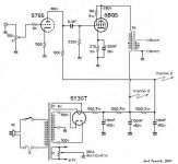
Joel's 5755/6bq5
Hi Joel,
I was looking at your subject amp and wondered if you had any hum with that PSU? Don't need a choke?
Also, are you operating your 84's at about 6.75v bias and 275v on the plate (round numbers)?
Just trying to learn a bit,
Rick
Hi Joel,
I was looking at your subject amp and wondered if you had any hum with that PSU? Don't need a choke?
Also, are you operating your 84's at about 6.75v bias and 275v on the plate (round numbers)?
Just trying to learn a bit,
Rick
Re: Joel's 5755/6bq5
No hum at all (and I have VERY efficient speakers as well!). You don't need a choke because it's a low current swing class A amplifier. But it never hurts to add one😉 , if you have the space and money. But I don't feel this amp is lacking sonically by not using one.
Actually closer to 9V bias, and exactly 250V on the plates.
Remember that a 6BQ5 in triode mode will draw around 34mA.
fragman56 said:I was looking at your subject amp and wondered if you had any hum with that PSU? Don't need a choke?
No hum at all (and I have VERY efficient speakers as well!). You don't need a choke because it's a low current swing class A amplifier. But it never hurts to add one😉 , if you have the space and money. But I don't feel this amp is lacking sonically by not using one.
Also, are you operating your 84's at about 6.75v bias and 275v on the plate (round numbers)?
Actually closer to 9V bias, and exactly 250V on the plates.
Remember that a 6BQ5 in triode mode will draw around 34mA.
Bridge vs tube rectifier
Is it common to have more hum with a full-wave bridge than with a tube rectifier all things being equal? That is, same power trans, caps, etc.
Rick
Is it common to have more hum with a full-wave bridge than with a tube rectifier all things being equal? That is, same power trans, caps, etc.
Rick
Not that I'm aware of. Voltage drop across each will be different of course, but that won't change relative hum levels.
Hum
If you model it, you'll see more hum on the SS bridge.
The reason is that the tube rectifier has some resitance built in (that's good and bad). If you were to add that equivalent resisitance in the form of a series resistor, the hum would be the same. But the power supply regulation (with load change) would be poorer.
- Status
- Not open for further replies.
- Home
- Amplifiers
- Tubes / Valves
- learning, building and testing tube amp