can't blame jens for his reaction, i just wish he'd reconsider.
more than the legal issues, i guess what could be playing in the back of his mind is that, with such an excellent design available from his website, who's to stop unscrupolous entitities cashing on on those designs that were originally intended for diy'ers.
piracy is worldwide, i guess that is the major issue...
JensRasmussen said:Hi All,
I have decided to close this project due to possible copyright infringements issues pointed out in an other Leach Super Amp thread.
This means that I will publish no layout for this amp and I will remove the Leach amp PCB production files + PDFs from my website in the near future.
Please excuse me for wasting your precious time – Moderators please terminate this thread – thank you.
Please don't contact me for boards or data - none will be provided - thank you.
\Jens
Dr. Leach encourages people to use his design, especially do it yourself'ers who do not make a profit. He publishes them on his open website and they are apparently public domain. Just ask him if he minds yet another group of audiophiles trying out his ideas; I will myself.
Out of respect, we should attribute the original design concept to him, of course. I really see the detailed implementation as a collective effort for the good of audio design. I suspect a few grad students had a hand in it too. Still, I know it is a matter of some pride for him that this design concept was so optimal that it is still highly praised for outstanding sound and reliability, and is still being built by folks around the world -- even after about 30 years.
We engineers get great satisfaction from "doing it right the first time", it is more art than science. The core design of the Leach Amp has not changed much in 30 years, proving that the design concept was spot on. That has got to be a source of great intangible reward for Dr. Leach, and I suspect he would be just delighted if more do it yourself'ers would clone it.
Dr. Leach publishes artwork for his Super Amp board to the public on the web. By doing so, he encourages you to make your own -- and indeed you must if you want to build the Leach Super Amp since he does not sell the boards. I think it would be tacky to make a profit from a Leach Amp clone, even if probably completely legal. I would never do that.
Frankly, it would be trivial to make some minor changes and sidestep any credible copyright issues, but I don't do this for profit and I prefer to stay very close to the proven design. "If it ain't broke, don't fix it." In this case, not only is it "not broke", it is highly tuned and optimized, with solid protection circuitry and conservatively rated parts throughout. It's bulletproof and sounds good too.
I have been an audiophile for a many years, and still own an example of the predecessor design for this amp, a JBL T circuit 400SE, one of the first to use true complementary symmetry in the output stage. I bought it new in 1969. It still works as it should, putting out 55 watts per channel. But Dr. Leach vastly improved the sonics of this design, by using a better front end with reduced gain bandwidth, contrary to the popular wisdom of the era. It worked well then and still works well today.
Motorola published an Application Note AN1308 in 1992 which is the Leach Amp design, using modern plastic output transistors. You can find it on the web here:
http://www.eetasia.com/ART_8800067721_499501_80e36c2a_no.HTM
So these ideas are no secret in the industry. After all, they have been around for more than 30 years. Most competent audio design electrical engineers are quite familiar with them. So there are no copyright issues here, this is all public domain. Still, it is brilliant work that should be appreciated by all. The best way I can see to do that is build a clone using the ideas. Sincere flattery indeed.
I think that this is the reason of the forum..
To help eachother with some projects, problems, questions...

A group of people in this forum has started the "evolution" of a project.
This is part of this forum i think...
There is no legal or copyright problems with this projects by me opinion!!
If you take a look at Mr. JensRasmussen PCB, at δ-audio you'll see that on the PCB it says "NON PROFIT DESIGN" BASED ON THE ORIGINAL DESIGN BY W.MASHALL LEACH"!!!!
It seams that some people doesn't understand that...
Anyway....
Hope that Jens don't stop this Project! For Dr.Leach funs first and for Jens effort after!🙁
To help eachother with some projects, problems, questions...
A group of people in this forum has started the "evolution" of a project.
This is part of this forum i think...
There is no legal or copyright problems with this projects by me opinion!!
If you take a look at Mr. JensRasmussen PCB, at δ-audio you'll see that on the PCB it says "NON PROFIT DESIGN" BASED ON THE ORIGINAL DESIGN BY W.MASHALL LEACH"!!!!
It seams that some people doesn't understand that...
Anyway....
Hope that Jens don't stop this Project! For Dr.Leach funs first and for Jens effort after!🙁
Oh man Jens,
Your bumming me out. I have been following your progress on this since the very beginning. Your 6 device boards were a thing of beauty and I still listen to that amp all the time. I surely hope you will reconsider.
Blessings, Terry
Your bumming me out. I have been following your progress on this since the very beginning. Your 6 device boards were a thing of beauty and I still listen to that amp all the time. I surely hope you will reconsider.
Blessings, Terry
"In Praise of Older .... Amp Designs"
Or: "Why the Leach Amp sounds Good"
Here is a list of some of the design choices that in my opinion made the Leach Amp sound good and why they matter.
1. The biggie: Low gain bandwidth for better stability on transients. Extensive use of local negative feedback everywhere so that global feedback can be low but still permit the amp to have acceptable distortion. Examples: input differential pairs use high value (300 ohm) emitter resistors, VAS has large emitter (390 ohm total) resistor, emitter follower output stage has gain less than 1 due to 100% local negative feedback. Cascoded input for reduced Miller effect on highs and reduced Early effect. Stability is so good that a 10pF Miller cap on the VAS is all that is needed to stabilize the amp.
2. Passive input bandpass filter: Rolls off the input highs at a relatively low frequency so the feedback loop can be stable. This relates to 1 above and is an important subtle detail.
3. Split feedback network: Feedforward compensation from the pre-driver stage for highs, and its dual, low-passed feedback from the output. Because the output stage is bipolar, it will always be much slower than the rest of the amp, and feedback from the output actually reduces stability at high frequencies. The predriver is a safe pickoff point for feedforward compensation.
4. Physical layout done well: A whole bunch of important little things. Input and output stages well separated physically, signal and power grounds connected separately to single point at power supply, output Zobel network placed on speaker output binding posts with separate ground return to single point ground. By the way, you must use single point ground in the system as well for minimum ground loop noise.
5. Conservative design: all parts used well below rating, output stage is a triple for good performance from even low gain output transistors, output transistors are reverse biased during cutoff for better SOA and lower distortion, no transistors ever saturate so recovery from overdrive is quick, base stopper resistors on the outputs, excellent output bias thermal tracking design (even if a bit old fashioned), overload protection on VAS and output stage, diode clamps on output to clamp inductive transients, Zoble network and damped output inductor for stability with reactive loads, well filtered DC for front end, no need for matching or critical adjustments, no expensive, rare or sole source parts.
There are a few things I might choose to do differently, but in general these were a lot of good design decisions yielding an excellent compromise of stability, low distortion, reliability, low cost, and great sound.
For a do it yourselfer, this is a very safe, conservative design that sounds much better than most of the "high end' product sold today. The absolute distortion measurements are not impressive, but your ears will tell you the truth: this design sounds great. People who love MUSIC love this amp. Novices can confidently build it and expect it to work well (thousands already have).
That's why I don't think we should kill this discussion. It was published in Audio magazine 30 years ago, it was made into a Heathkit amp in the 80s, it was published as Motorola AN1308 in 1992, and it is still published on the Leach website; it is hard to imagine a better example of a public domain design.
Even if you don't build the amp, you can learn a lot from studying it, and I think that is important -- and as a teacher Dr. Leach would probably agree. But this is your group and you all should decide. I guess the thing to do is have a poll, what the heck.
Hmmm... I can't figure out how to start a poll. OK, I'll post this and do my homework on polling later. It will be simple: "Lock thread or don't?" To be continued....
Hello Folks,
Seems there's lots of diy'ers that want to continue this project.
Please count me as one who also wants this excellent project to
find its full fruition.
Lots of opinions from what may be fairly described as arm chair lawyers in my humble opinion. At least no one has quoted any case law as yet.
We all may poll each other about this subject until dooms day and decide to continue in spite of the fact the design is not OUR property.
Why not do the most obvious thing?
Simply ask the author for his consent.
Perhaps a few folks sending polite e-mail messages will get his attention and permission. Surely no one here is really thinking of stealing this respected engineers creation just because a poll finds it a popular idea. My daddy would have taken me out behind the wood pile for doing such a thing.
Shame on the moderators for not taking notice of this explosive issue.
Just my two cents worth.
I checked the FAQ, and it says I can post a poll using the following example and instructions, but I don't see the 'Yes! post a poll" checkbox. Another mystery for greater minds to solve. Here is what the FAQ says:
What is your favorite color?
Red
Blue
Yellow
Green
Sky-blue pink with yellow spots
To create a poll when you post a new thread, simply click the 'Yes! post a poll' checkbox at the bottom of the page, and set the number of possible responses you want to include.
OK, folks, just post a yes or no post. Yes=Lock thread. No=Don't.
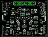
As a tease, I did my own version of the Leach Super Amp, on either two or three boards -- with 8 or 16 output transistors, your option. The output board gets sheared in two, but I decided to make it one I expect to need a pair per driver board anyway. Board size is 80x100mm, since the freeware Eagle 4.16 I am using is limited to this size max. This amp fits on a flat heatsink 100x160mm or 100x240mm, depending on whether you choose 8 (original recipe) or 16 outputs (extra spicy).
What is your favorite color?
Red
Blue
Yellow
Green
Sky-blue pink with yellow spots
To create a poll when you post a new thread, simply click the 'Yes! post a poll' checkbox at the bottom of the page, and set the number of possible responses you want to include.
OK, folks, just post a yes or no post. Yes=Lock thread. No=Don't.
As a tease, I did my own version of the Leach Super Amp, on either two or three boards -- with 8 or 16 output transistors, your option. The output board gets sheared in two, but I decided to make it one I expect to need a pair per driver board anyway. Board size is 80x100mm, since the freeware Eagle 4.16 I am using is limited to this size max. This amp fits on a flat heatsink 100x160mm or 100x240mm, depending on whether you choose 8 (original recipe) or 16 outputs (extra spicy).
Attachments
no, don't lock this thread please!
slowhand couldn't have said it any better, this leach super amp is a classic, in a class all by itself.
slowhand couldn't have said it any better, this leach super amp is a classic, in a class all by itself.
geezer1944 said:Hello Folks,
Seems there's lots of diy'ers that want to continue this project.
Please count me as one who also wants this excellent project to
find its full fruition.
Lots of opinions from what may be fairly described as arm chair lawyers in my humble opinion. At least no one has quoted any case law as yet.
We all may poll each other about this subject until dooms day and decide to continue in spite of the fact the design is not OUR property.
Why not do the most obvious thing?
Simply ask the author for his consent.
Perhaps a few folks sending polite e-mail messages will get his attention and permission. Surely no one here is really thinking of stealing this respected engineers creation just because a poll finds it a popular idea. My daddy would have taken me out behind the wood pile for doing such a thing.
Shame on the moderators for not taking notice of this explosive issue.
Just my two cents worth.
I emailed Mr. Leach during least years Leach amp GB, I got no reply. I suspect that if Mr. Leach feels that his copyrights has been violated we would have heard something a long time ago.
To be honest I got sick of the endless argumentation from people not really participating in the project.
As with everything in life building amps is a compromise and nothing is all good or all bad!
My compromise it that I pull out for reasons that should be clear to most readers of several Leach amp threads. It is taking too much out of me to still be fun. I’m sorry to have been taking your time without any substantial result to show for it.
I wish you luck with getting this together – may you all have great amps!
I will not comment on the current design, but if a designer chooses to release a project, I will be happy to give my inputs via email.
\Jens
Hi Slowhands,
I thought you were talking about me when I read your nickname.
4pair output board fitted into about 7sq inch. Well done!!
Note you can fit the power transistors from below and then bend them over to lay flat onto a 150 by 125 heatsink.
You don't need the spacer blocks that Leach shows.
However, if the power transistor pads were swapped so that the metal faces were towards each other then the transistors could be folded in towards each other and allow a lower height heatsink to be used and in turn allow a lower case to fit (3u?).
When you come to do the driver board, can you layout the traces so that the drivers (To220) can also be replaced with To126 by inserting three extra holes but with the order swapped?
2sb649/d669 make excellent drivers. But not for 2ohm speakers.
I have had contact with Prof. Leach so your email may have get lost somewhere in the process. Maybe you should try once more?JensRasmussen said:I emailed Mr. Leach during least years Leach amp GB, I got no reply. I suspect that if Mr. Leach feels that his copyrights has been violated we would have heard something a long time ago.
Jens if you are in charge you don't have to please everyone. Write down the specifications or wishes and then you'll deside how things should look like. Make sure that you are pleased yourself first. So far I think you have done an excellent job in pcb design and the community need fully professional pcb's I think. If you look around, how many similar amp projects are around?
i fully agree.
jens, we need your support.
specially those new in the field.
i can't afford those expensive amps and therefore relying in this forum.
i hope that Jens reconsider.
jens, we need your support.
specially those new in the field.
i can't afford those expensive amps and therefore relying in this forum.
i hope that Jens reconsider.
JensRasmussen said:
I emailed Mr. Leach during least years Leach amp GB, I got no reply. I suspect that if Mr. Leach feels that his copyrights has been violated we would have heard something a long time ago.
To be honest I got sick of the endless argumentation from people not really participating in the project.
As with everything in life building amps is a compromise and nothing is all good or all bad!
My compromise it that I pull out for reasons that should be clear to most readers of several Leach amp threads. It is taking too much out of me to still be fun. I’m sorry to have been taking your time without any substantial result to show for it.
I wish you luck with getting this together – may you all have great amps!
I will not comment on the current design, but if a designer chooses to release a project, I will be happy to give my inputs via email.
\Jens
Hi Jens,
My hope is that you continue, if necessary, on your own and complete this design. Then once you've heard it you will be excited about sharing it with the rest of us. I built one using Dr. Leach's design, etching my own boards, and never got it to work. I have full confidence that I will be able to build one that works using PCBs of your design. The boards you designed for the Low TIM worked wonderfully. I even gave two of them to a friend who wanted to get into the hobby, knowing that his chance for success would be very high using your boards.
Please give some thought to at least following through with the design. You are so close already.
Blessings, Terry
Mr. Jens,
How hard can it be to compose a polite e-mail/letter to the professor?
Life can be difficult, but really sir, this is a no brainer.
Now you may have to wait a bit for a reply. My grandson is on spring break from college. So we could expect the good professor might also be away from work.
Nothing succeeds like persistence.
Elvin
sometimes, silence means yes.... perhaps if prof. leach had objections, he would have responded like so...
i say, please go ahead with this project. i do not mind waiting for another year....this is DIY!!!
i say, please go ahead with this project. i do not mind waiting for another year....this is DIY!!!
Tony said:sometimes, silence means yes.... perhaps if prof. leach had objections, he would have responded like so...
i say, please go ahead with this project. i do not mind waiting for another year....this is DIY!!!
He gets a ton of email, and might miss yours. I will contact him, and he will give a go ahead, I'm sure. I've had 4 replies from Dr. Leach over the 6 years. Three were about buying boards for the Leach Amp original. One was a reply to a technical comment on the amp, which I'll tell you about now.
I couldn't see how the protection circuit on the VAS would ever do anything, because the VAS has limited voltage drive to begin with, which is an implicit current limit. He thought it was still a good idea. I still respectfully disagree. He is not likely to change much in this design, it's a matter of pride in getting it right the first time. My point was a trivial one, the amp works just fine as it is designed even if the protector never triggers. But he is really good about replying, he did not have to. I never was his student, just an audio nut like so many he must hear from.
I did a little layout of the original Leach Amp too, using plastic transistors. Getting rid of the wires to the output stage is a very good thing. I mounted the drivers, and the Vbe multiplier on the main heat sink. The board is 3 inches by 4, half the original size.
I made some minor changes that simplify it a bit. So technically it's not a Leach Amp exactly. I changed the Vbe multiplier to a single transistor (MJE340 on the heat sink), deleting the diode string. I use only one Zener for the 40V (but put the holes in for two if you must). I added an optional input DC blocking capacitor, and optional resistor between signal ground and the input ground. I changed the the TO-5 xtors to TO126, and the outputs to TO264 plastics. Much easier to wire up and to heatsink on a simple flat plate.
Look at the attached silkscreen. You have to imagine all the vertically mounted transistors on the border are really laid down on the underside of the board, fixed to the flat heatsink. I could not show them that way in my freeware version of Eagle (they don't let you use a bigger area), but of course that is the way they should be. So there should 7 little imaginary wings on the board, the transistors on the main heatsink: the 4 outputs, the 2 drivers and the Vbe Multiplier. Incidentally, for power connectors I used the type on hard drives, cuz I have a lot of old cables for them from obsolete PC power supplies. Recycling.
Sorry for the limitations of the program, or my pocketbook really. I guess I should get the Pro version one of these days. I'm still not sure which package is the best. Some like EasyPC instead. I've used Orcad too, all have their good points and faults.
I guess the moderators did not kill this thread yet, so we can go ahead and discuss the Super Amp Re layout. I don't think it should take a year. But at least a month to shake out protos is the minimum. If you all want, we can still go ahead, and soon I hope.
Attachments
Hi Slowhands,
I think you are mistaken
Imagine the situation when the output is connected to almost zero resistance to ground and the output protection is triggered.
The base of each driver transistor is alternately connected to output rail and in turn to ground via the accidental short.
The VAS now has Vrail to ground across it and is trying to flow current to pull the driver base back up to normal voltage level. The triggered protection transistor is saturated and has at most a few hundred mV across it and wins this tug of war.
Bang and lots of magic smoke from the VAS.
Even the scenario of a very low load say 3ohms for a 4ohm speaker with the output protection active. Now the VAS is connected via the 3ohm load to ground during each alternate cycle. Again the VAS will fail.
The VAS protection is a constant current source that only becomes active when the VAS tries to push excessive current into the output stage. When in constant current (protected) mode the dissipation will be Vrail times ccs value and the VAS should be selected and heatsinked for this duty.
I would suggest a ccs limit of about 3 times the normal VAS quiescent current. Prof Leach's choice for the sensing resistor is a bit low @ 33r (about 20mA), I am using 56r (about 11mA) for R24 & R25 in the Leach clone (4.5)
I think you are mistaken
the VAS has limited voltage drive to begin with, which is an implicit current limit.
Imagine the situation when the output is connected to almost zero resistance to ground and the output protection is triggered.
The base of each driver transistor is alternately connected to output rail and in turn to ground via the accidental short.
The VAS now has Vrail to ground across it and is trying to flow current to pull the driver base back up to normal voltage level. The triggered protection transistor is saturated and has at most a few hundred mV across it and wins this tug of war.
Bang and lots of magic smoke from the VAS.
Even the scenario of a very low load say 3ohms for a 4ohm speaker with the output protection active. Now the VAS is connected via the 3ohm load to ground during each alternate cycle. Again the VAS will fail.
The VAS protection is a constant current source that only becomes active when the VAS tries to push excessive current into the output stage. When in constant current (protected) mode the dissipation will be Vrail times ccs value and the VAS should be selected and heatsinked for this duty.
I would suggest a ccs limit of about 3 times the normal VAS quiescent current. Prof Leach's choice for the sensing resistor is a bit low @ 33r (about 20mA), I am using 56r (about 11mA) for R24 & R25 in the Leach clone (4.5)
- Status
- Not open for further replies.
- Home
- Amplifiers
- Solid State
- Leach Super Amp Pcb Re-Design (LSAPRD)