Is this measured while arduino is clicking relays? If not, please repeat the measurements.
Next, disconnect display and encoder and see if you still see relays going crazy.
Next, disconnect display and encoder and see if you still see relays going crazy.
Neb, still 4.98V when relays are clicking.
When only display is detached, clicking stops.
When encoder only is detached, clicking continues.
I checked display wireing - should be ok.
Ernst
When only display is detached, clicking stops.
When encoder only is detached, clicking continues.
I checked display wireing - should be ok.
Ernst
Looks like display may be messing with i2c bus or d+ power line, both are common for arduino and oled. Try to put 1000uf cap on digital 5v line. Try another oled if you have it.
Neb, thank you! It works now. [emoji4] I'm waiting to finish calibration.
The 1000 uF were the solution.
Cheers, Ernst
The 1000 uF were the solution.
Cheers, Ernst
Last edited:
Set Paramters
Neb,
when I want to set the minimum resistance LDR values, it seems that it is not possible. When I in the menue go further down from Set Load Impedance, the screen goes black and I have to start again. Don't know how to proceed here.
Manual says, one should measure and put values in, except one gets a finished version. Can you guide here.
Cheers
Ernst
You haven't fixed the problem. It should work without 1000uF capacitor. It seems that your oled has issues and injecting garbage into power line.
You haven't fixed the problem. It should work without 1000uF capacitor. It seems that your oled has issues and injecting garbage into power line.
Do you think, this might be resoponsible not to be able to enter point 4 g (set parameters / LSE, LSH, RSE, RSH Minimum Resistance) in your user manual?
My display is just the one you linked to in your BOM.
Ernst
It’s either faulty display or something else messing with 5v power line, or maybe power line itself. 5v on d+ has to be absolutely stable and free of any noise.
Neb, wish you a fine Sunday!
First I checkted all the naked voltages with my scope. All three are ok.
Plugged in everything I have heavy signals on D+. After pulling out the display cable there is still some weird signal to see, yet it is much smaller. Then I soldered a 220µF cap directly to the display. The signal came down to 15mV and everything seems to work.
I flashed the Nano once again, and now I could go through the menue and set all things, including the LDR min resistance. I am now calibrating the thing again.
So I'm not sure, that the display is the reason, but I will order a new one. Do you accidently have a 1602 you do not need? I would be happy if you sold it to me.
Cheers, Ernst
Neb, wish you a fine Sunday!
First I checkted all the naked voltages with my scope. All three are ok.
Plugged in everything I have heavy signals on D+. After pulling out the display cable there is still some weird signal to see, yet it is much smaller. Then I soldered a 220µF cap directly to the display. The signal came down to 15mV and everything seems to work.
I flashed the Nano once again, and now I could go through the menue and set all things, including the LDR min resistance. I am now calibrating the thing again.
So I'm not sure, that the display is the reason, but I will order a new one. Do you accidently have a 1602 you do not need? I would be happy if you sold it to me.
Cheers, Ernst
I'm not sure display is defective. It might be like that by (bad) design. I had also few which were injecting noise into power line, so ideally, OLED should be on it's own power rail. Wide.hk are usually OK to replace it in case of malfunction.
Last edited:
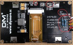
I managed to make these OLEDs from aliexpress work with my code:
BLUE 2.42" Digital LCD Screen 12864 128X64 OLED Display Module C51 Board For Arduino SSD1309 STM32 Diy Electronic 2.42 inch-in LCD Modules from Electronic Components & Supplies on Aliexpress.com | Alibaba Group
There are hardware modifications required which I can post here if there is interest. They are slightly cheaper then the ones from wide.hk.
Please post the modd to be done for that Oled, I have two of that from other projecto, they are fine.
Please post the modd to be done for that Oled, I have two of that from other projecto, they are fine.
R4 - remove
R3, R5, R7 - OR (short with blob of solder)
DC - connect to VCC with 10K resistor (pullup)
RES - connect to VCC with 10K resistor (pullup) and connect to RST on Arduino.
Thanks, will it work with the same firmware, or need New version?
100% compatible with existing firmware for graphic oled (with "G" in the name)
- Home
- Source & Line
- Analog Line Level
- LDR Pre MkII - LDR volume control and I/O switching

