Hi folks
I am trying to come up with an LC filter for the output of a linear power supply.
The output is switchable between 6v and 12vc DC, and I need a steady 2A out of the filter with a frequency cut off as low as possible.
If someone has a solution, would it be possible to explain the method used to reach that solution, as I don't have a lot of experience with LC filters.
Thanks
"Frequency cutoff as low as possible" is not a spec for a filter so you can't start designing from that. First you need to decide what you want the filter to filter out: ripple, noise, interference or what? We can't offer a solution if you haven't posed a problem.
Start by winding a coil about the size of your house, just much larger, buy the whole stock of high-farad caps from RS, Mouser, Farnell, etc and you will end up with a reasonable real-world approximation of your spec: a cut-off Freq in the µHz rangeand I need a steady 2A out of the filter with a frequency cut off as low as possible.
When I say as low as possible, I mean I want to filter out as much DC ripple, noise and RF as possible.
Seeing as it is impossible to achieve that, I'm looking for an LC filter that comes very close, yet still of a practical size.
I have found a commercially available filter that would work, yet the output current is only 1A, I would prefer a steady output of 2A.
Seeing as it is impossible to achieve that, I'm looking for an LC filter that comes very close, yet still of a practical size.
I have found a commercially available filter that would work, yet the output current is only 1A, I would prefer a steady output of 2A.
Why not use a LM338 for a regulated supply? It has 5A output (up to 12A for short periods of time) and can be adjusted for 6v or 12v output. If you bypass the adjustment pin with a 10uf capacitor you get 75db ripple rejection at any output. Solid tantalum is best used due to low impedance even at high frequencies, just don't forget about protection diodes.
The dimensions I have to work with in the enclosure is 250x80x300. approximately.
I reckon a cut off frequency of 40hz would be enough.
The main goal is to have the supply resemble an ideal battery as much as possible, whilst taking into account the area available for parts.
The power supply will be used to power low current digital devices, but I would prefer an output of 2A to add some versatility.
Why not use a LM338 for a regulated supply? It has 5A output (up to 12A for short periods of time) and can be adjusted for 6v or 12v output. If you bypass the adjustment pin with a 10uf capacitor you get 75db ripple rejection at any output. Solid tantalum is best used due to low impedance even at high frequencies, just don't forget about protection diodes.
Thanks for the info, I will have a look at the datasheet. I had initially planned to have two separately regulated stages, but that sounds better and it will free up some board space.
JSmith1980 said:When I say as low as possible, I mean I want to filter out as much DC ripple, noise and RF as possible.
40Hz cutoff will remove very little ripple.I reckon a cut off frequency of 40hz would be enough.
To design a PSU you need a specification. "Noise/ripple as low as possible" is not a specification. "40Hz cutoff" is a filter specification but not a very useful one if you are concerned about ripple. "Like an ideal battery" is not a specification.
40Hz cutoff will remove very little ripple.
To design a PSU you need a specification. "Noise/ripple as low as possible" is not a specification. "40Hz cutoff" is a filter specification but not a very useful one if you are concerned about ripple. "Like an ideal battery" is not a specification.
Like I had mentioned in my initial post, I don't have a lot of experience with LC filters, I am learning as I go. Surely you must have an idea of what I am looking for, from the information I have given so far.
I am looking for a power supply that than can deliver a steady 6v or 12v with a steady 2A of current without noise, RFI and minimal DC ripple.
The first part is in place, I have the DC voltage and current. All I need to do now is eradicate unwanted ripple, noise and RFI from that DC, whilst keeping the device within the dimension I have specified.
Low frequency ripple is easily delt with by the sand, no need to use a **Massive** LC filter to help with that, if you need quieter pick a better regulator, 7812 is not exactly state of the art you know.
Low frequency noise is also mostly a sand related issue, ferrite is mostly good for the MHz+ region where the regulators PSRR has taken a huge hit, but this is a linear supply so you shouldn't have significant issues there.
100nF on the regulator output is maybe a bit thin, a 1uF X7R would be more to my taste.
LC on a regulator board output is seldom a cure for much, I might see a common mode choke made with a couple of beads if I was working around radio transmitters, but no more then that.
Another reason to avoid massive LC networks, especially ones with large L after the regulator is that they can cause significant overshoot and potentially damage downstream circuits if the loaded Q is too high.
We cannot put numbers to it or suggest a design until you put numbers to your requirements (And, "As low as possible" is not a number).
You usually see choke filters as very local things next to sensitive clock generators or data converters on a board, they are not popular at the output of power supplies for logic (And there is a reason for this).
Regards, Dan.
Low frequency ripple is easily delt with by the sand, no need to use a **Massive** LC filter to help with that, if you need quieter pick a better regulator, 7812 is not exactly state of the art you know.
Low frequency noise is also mostly a sand related issue, ferrite is mostly good for the MHz+ region where the regulators PSRR has taken a huge hit, but this is a linear supply so you shouldn't have significant issues there.
100nF on the regulator output is maybe a bit thin, a 1uF X7R would be more to my taste.
LC on a regulator board output is seldom a cure for much, I might see a common mode choke made with a couple of beads if I was working around radio transmitters, but no more then that.
Another reason to avoid massive LC networks, especially ones with large L after the regulator is that they can cause significant overshoot and potentially damage downstream circuits if the loaded Q is too high.
We cannot put numbers to it or suggest a design until you put numbers to your requirements (And, "As low as possible" is not a number).
You usually see choke filters as very local things next to sensitive clock generators or data converters on a board, they are not popular at the output of power supplies for logic (And there is a reason for this).
Regards, Dan.
I see, so you reckon that it is best to rely on the local choke on the board of the load device, instead of adding one to the power supply? I plan to use an RF choke at the input of the power supply to prevent RF coming in through the AC. It's combined with the IEC socket.
I may just use a better voltage regulator and add a mixture of electrolytic, tantalum and ceramic capacitors at the output in the remaining board space, to deal with any noise.
Thanks.
http://www.cwsbytemark.com/images/OD%20330.pdf
Looking at the above DS for toroids, you can use the Sendust 125u to make your series inductor and wind 74 turns of 22AWG giving around 500uH at 2A (inductance sags at higher currents). For the shunt caps I reckon you'll need 16 * 4700uF 16V in parallel. This gives a turnover frequency around 20Hz.
Looking at the above DS for toroids, you can use the Sendust 125u to make your series inductor and wind 74 turns of 22AWG giving around 500uH at 2A (inductance sags at higher currents). For the shunt caps I reckon you'll need 16 * 4700uF 16V in parallel. This gives a turnover frequency around 20Hz.
http://www.cwsbytemark.com/images/OD 330.pdf
Looking at the above DS for toroids, you can use the Sendust 125u to make your series inductor and wind 74 turns of 22AWG giving around 500uH at 2A (inductance sags at higher currents). For the shunt caps I reckon you'll need 16 * 4700uF 16V in parallel. This gives a turnover frequency around 20Hz.
I have found a commercially available toroid that meets the exact specification that you have mentioned. (500uH 22AWG) I would have a crack at winding it myself, but a commercially available one might be bit more accurate. I will also have plenty room on the board for the capacitors.
When you say wire the caps in parallel with the inductors, do you mean 16 x 4700uF for +12v and another 16 x 4700uF for 0v?
Thanks for the info, much appreciated.
No I didn't mean 'wire the caps in parallel with the inductors' rather 'wire all the caps in parallel with each other'. Only one inductor is needed, 16 paralleled caps.
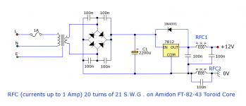
The toroid goes where RFC1 is on the schematic you've shown, and the 4700uFs replace the 100nF shown connecting to +12V. Delete the other RFC (RFC2) - it doesn't seem to me to serve a useful function. Replace it with a wire and delete the paralleled 100nF too.
If you really want ripple reduction then use CLCLC prior to the regulator (in place of your single 2200uF). The output filter's purpose is really to reduce the 7812 noise.
No, I haven't a clue. You haven't told us what you need, and what your existing PSU arrangements can deliver. You are asking us "How much string do I need to add to make this string (I already have) as long as possible?". What you should say is "My string is 2m long. I need 7m. How much should I add?".JSmith1980 said:Surely you must have an idea of what I am looking for, from the information I have given so far.
You are still using words like "steady", "without noise", "minimal ripple". There are two ways to proceed: use numbers and do design, or build a prototype and modify it until it does what you need. Some combination of the two is possible and common. What you can't do is design without numbers.
At last, some progress! If that circuit almost satisfies your need then you just need to redesign the output filter to pass more current. Note that the filter will do nothing whatsover to ripple. It may reduce RF a little, although I am puzzled why a tuned circuit is included in the ground connection - maybe the designer was a bit confused, or had some special requirement in mind?Here is an example circuit of what I am looking for. As a result of the inductive filter at the output, the circuit can only deliver 1A. I need 2A.
No I didn't mean 'wire the caps in parallel with the inductors' rather 'wire all the caps in parallel with each other'. Only one inductor is needed, 16 paralleled caps.
The toroid goes where RFC1 is on the schematic you've shown, and the 4700uFs replace the 100nF shown connecting to +12V. Delete the other RFC (RFC2) - it doesn't seem to me to serve a useful function. Replace it with a wire and delete the paralleled 100nF too.
If you really want ripple reduction then use CLCLC prior to the regulator (in place of your single 2200uF). The output filter's purpose is really to reduce the 7812 noise.
Okay. I have put in the changes. I will replace the regulator with an LM388. I am going to use that suggestion about bypassing the adjustment pin with a 10uF capacitor to get a 75db ripple rejection once I have read through the data sheet.
Attachments
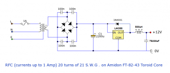
LM338 needs resistors to set its output voltage, its not a fixed voltage device. I suggest using LM350 as from the DS it looks to be lower noise. Bypass with 1000uF to get even lower noise.
post18
remove the 4 capacitors across the Bridge rectifier.
This is more likely to increase the chance of ripple/ringing on the output.
Try without. If there is some ringing then add a snubber (R+C) across the transformer secondary, i.e. across ~~.
1A Mains fuse is quite high.
A T1A will supply upto 230VA transformer.
You may need to add HF decoupling across the input of the reg and also across the output of the reg. What does the datasheet say?
- Status
- Not open for further replies.
- Home
- Amplifiers
- Power Supplies
- LC Low Pass Filter Design.