you meant 300GHz.
h= hecto
Hz = Hertz.
When the unit of measurement (not multiplier) is using a person Name then one uses the capital form of the letter.
eg, C, K, S, W, etc.
h= hecto
Hz = Hertz.
When the unit of measurement (not multiplier) is using a person Name then one uses the capital form of the letter.
eg, C, K, S, W, etc.
The enclosure is capacitively coupled to "Earth"The enclosure of the chassis will be star connected
That capacitance is what gives the low impedance to very high frequencies. A cable can NEVER get as low in impedance for any of HF, VHF, UHF and beyond.
we finally get to find out what the PSU is supplying in post40 !!!!!The power supply will be used for powering various digital devices
Digital circuits NEED local decoupling to maintain low impedance between Digital Power Plane/s and Digital Ground plane/s
That will require many low esr electrolytics spread around and between digital devices and many ceramics located at every power pin of every digital device.
The "external PSU" simply has nothing it can do to reduce the glitches on the power planes.
The best it can do is to maintain a near constant voltage (at relatively low frequency) that ensures the Power does not stray outside the limits specified in the datasheets.
You are wasting our time and your resources with the proposals you have presented so far.
It is cheaper to buy Henry Ott's book than to build what you propose.
Last edited:
we finally get to find out what the PSU is supplying in post40 !!!!!
Digital circuits NEED local decoupling to maintain low impedance between Digital Power Plane/s and Digital Ground plane/s
That will require many low esr electrolytics spread around and between digital devices and many ceramics located at every power pin of every digital device.
The "external PSU" simply has nothing it can do to reduce the glitches on the power planes.
The best it can do is to maintain a near constant voltage (at relatively low frequency) that ensures the Power does not stray outside the limits specified in the datasheets.
You are wasting our time and your resources with the proposals you have presented so far.
It is cheaper to buy Henry Ott's book than to build what you propose.
I do appreciate the help, but I don't believe it's a waste at all. A well built PSU will always be of greater benefit than the standard plugin noisy switch mode type PSU that only exists to make a device basically operational.
If I can build a PSU that delivers power well within the PSR of the load device, it will be worth it.
I will have a look for that book on Amazon.
If you want to build low pass filters which will be good up to 300GHz then you have a very steep learning curve ahead of you. I have been an audio/radio/electronics enthusiast for about 45 years (and have a PhD in EE, and a ham licence) but I would have to do a lot of reading and tinkering before I could build a 300GHz filter. I would also need to spend a small fortune on test equipment.
Running before walking always ends in tears. Good luck!
Running before walking always ends in tears. Good luck!
Between the self-appointed educators, the axe-grinders and the comedians, it's pretty hard to get a straight answer around here.
I know the guy is trying to run before he can walk, but that's not good reason to proffer a banana-skin. Just tell him the basics of PSU design or point him to The Art of Electronics: Amazon.co.uk: Paul Horowitz, Winfield Hill: Books or a filter calculator LC Ripple Filter Calculator
OP, google is your friend.
Last edited:
Horrowitz and Hill will not give him the guidance he needs to create a good Digital PCB relative to power plane/s and local decoupling.
There is a short section starting on p355, Interference: shielding and grounding.
No diagram shows decoupling on the power pins of any IC/device.
There is a long chapter on digital electronics.
P554, fig8.96 shows local decoupling with the title: It's always a good idea to use robust low-inductance wiring with liberal use of bypass capacitors.
As far as I can see that's their advice.
Between the self-appointed educators, the axe-grinders and the comedians, it's pretty hard to get a straight answer around here.
I know the guy is trying to run before he can walk, but that's not good reason to proffer a banana-skin. Just tell him the basics of PSU design or point him to The Art of Electronics: Amazon.co.uk: Paul Horowitz, Winfield Hill: Books or a filter calculator LC Ripple Filter Calculator
OP, google is your friend.
Thanks counter culture.
I had mentioned at the beginning of the thread that I'm learning as I go, surely it's not too much to ask that we try to keep the thread constructive?
I actually do own the book called 'The Art Of Electronics'. The main issue with LC filters, is the fact that in reality, all capacitors are not the same. As mentioned already, electrolytic caps are limited as to their frequency response, and are effectively useless after a few hundred kilohertz. Ceramics are effective for use at high frequencies, but their value of capacitance is so low, it would require a very high number of ceramic caps to reach the required value.
I have been reading up on ferrite beads, and it is possible to get an excellent level of high frequency attenuation up to 1GHz through the use of various types of ferrite beads in series, and without the space constraints of using as many capacitors.
Last edited:
Between the self-appointed educators
If you are referring to DF96, that is a very unreasonable accusation. If anything, he was 'appointed' by others, myself included. When you are reasonably well-versed in a subject, and someone comes along with clear and obvious understanding in excess of your own regarding that subject, you respect and admire them. This is the first I heard that DF96 has a PhD, and to be honest it doesn't surprise me. His posts reflect that level of competence.
I find too many posts in this forum from those who eschew education and credential. We would be well served to pay attention to his posts.
FWIW, cut my teeth on Horowitz and Hill back in college; a fantastic book. Really helped me build practical well-working circuits when its fundamental theory was followed.
This thread has moved from unstated requirements ("as XX as possible") to non-solutions ("here is a circuit diagram of something I am not going to build") to ridiculously onerous requirements ("must work up to 300GHz"). Under these conditions it is difficult to offer help, apart from repeatedly asking for a realistic requirement. As AndrewT noted, we reached post 40 before the application was mentioned.
This is not the place to teach the basics of PSU design, or filter design. The OP has now told us that he has access to Horowittz and Hill. Good, but that won't help him with microwave circuitry. I can't help him with microwave circuitry - there are others on here who could but I suspect they will find it difficult.
A realistic specification is needed. That is my repeated "constructive" comment. Given that, it may be possible to design a multi-section filter to provide the required wideband attenuation - if indeed such a wideband response is actually needed (which I doubt). Note that such a filter will probably include quite low value ceramic caps; probably tiny SMD devices.
It is characteristic of human nature that when someone brings bad news ("it is much more complicated than you can imagine") the instinct of bystanders is to shoot the messenger.
This thread has moved from unstated requirements ("as XX as possible") to non-solutions ("here is a circuit diagram of something I am not going to build") to ridiculously onerous requirements ("must work up to 300GHz"). Under these conditions it is difficult to offer help, apart from repeatedly asking for a realistic requirement. As AndrewT noted, we reached post 40 before the application was mentioned.
This is not the place to teach the basics of PSU design, or filter design. The OP has now told us that he has access to Horowittz and Hill. Good, but that won't help him with microwave circuitry. I can't help him with microwave circuitry - there are others on here who could but I suspect they will find it difficult.
A realistic specification is needed. That is my repeated "constructive" comment. Given that, it may be possible to design a multi-section filter to provide the required wideband attenuation - if indeed such a wideband response is actually needed (which I doubt). Note that such a filter will probably include quite low value ceramic caps; probably tiny SMD devices.
It is characteristic of human nature that when someone brings bad news ("it is much more complicated than you can imagine") the instinct of bystanders is to shoot the messenger.
I am determined to build a power supply with a wideband filter, there is no doubt about it, that is why I have continued to post questions and suggestions in the hope of some practical and constructive feedback.
I never said "must work up to 300GHz". I said "I want to be sure that RFI is kept to a minimum level, that includes anything from 3Khz up to the 300GHz". I have now given the required output voltage (6v - 12v DC) and the current (2A), you know the application of the power supply (PSU for Digital Devices) and you know the board area I have to work with for the filter stage (250x80x300 WxHxD) As I mentioned in my initial post, I am learning as I go, and that includes learning what is practical with my space restraints.
It's not the "bad news" itself that is the issue, it was the continual destructive criticism without putting forward any possible practical solutions. I posted in these forums looking for solutions, I could have found sarcastic, unhelpful remarks without even going into any forums.
If 300GHz is included in your design goals, it will in fact become the dominant issue: you'll have to skew all your tradeoffs (yes, a dirty word!) towards that goal, and as a consequence relax the other requirements, ie 100Hz and 20/20Khz audio band ones.I said "I want to be sure that RFI is kept to a minimum level, that includes anything from 3Khz up to the 300GHz".
If that is indeed your priority, why not, but personally that wouldn't be my choice.
Be aware that well before 300GHz, ferrites and other materials become mere lumps of lossy material akin to fired clay or similar: they have no useful properties anymore, and you have to resort to other and more subtle means of filtering unwanted frequencies. It is a very specialized domain in which most of the members of this forum (including myself) are incompetent
Other forums are more µW-centered, but I am afraid their members will react violently towards a demand what they will see as futile...
Thanks counter culture.
I actually do own the book called 'The Art Of Electronics'. The main issue with LC filters, is the fact that in reality, all capacitors are not the same. As mentioned already, electrolytic caps are limited as to their frequency response, and are effectively useless after a few hundred kilohertz. Ceramics are effective for use at high frequencies, but their value of capacitance is so low, it would require a very high number of ceramic caps to reach the required value.
I have been reading up on ferrite beads, and it is possible to get an excellent level of high frequency attenuation up to 1GHz through the use of various types of ferrite beads in series, and without the space constraints of using as many capacitors.
OK, you have Horowitz & Hill.
Electronics design is always a trade-off. Some things simply cannot be achieved simultaneously, and when price or space constraints are introduced, the range of the possible decreases.
The output of the bridge rectifier is 'lumpy'. In order to reduce the 'lumpiness', without significant loss of power, we can employ series inductors or parallel capacitors. A single capacitor may be employed, but more complex arrangements can reduce the residual (ripple). It is easy to see in the case of the single capacitor that the ripple attenuation will be directly related to the size of the capacitor (and the intrinsic impedances of the transformer, rectifier and load). There is no way to dispense with this capacitance other than to use inductance. Ferrite beads have no effect whatsoever at frequencies lower than a few hundred kHz. Inductors in the Henry range are required to have significant impact on features in the 100 or 120 Hz range, and the inductance must be at those frequencies.
So your first objective is to design something that achieves a ripple that is adequate to the requirements of the output of the client circuit, either in terms of hum or BER, depending on its PSRR. This cannot be neglected. When that is dealt with we can turn our attention to the HF.
Of course regulation remains an option.
The influence of component types is a difficult subject, because there are so many different types, with such diverse characteristics. For this reason, and others, we lean on the experience of others. We copy circuits that have worked before and we re-use the components that have worked before. Only when we have accumulated some experience of our own do we start to 'shoot for the moon' in performance terms, because by then we will have acquired some knowledge of the possible pitfalls.
It's certainly true that electrolytic capacitors are limited as to their frequency response, but it is not useful to lecture us:- 'The main issue with LC filters, is the fact that in reality, all capacitors are not the same.' I might equally respond that 'The main issue with LC filters is the fact that they use inductors.' We don't like inductors, you know.
Build a circuit or circuits to meet a specification such as I have outlined. Employ no exotic components, just conventional LC or RC filtering, with as many stages as you chose, or regulated. Any given capacitance or inductance can be split into sections and replicated CLCLC, CRCRC etc, achieving superior performance for the same total impedance. After about 4 stages there's not much point. By all means use electrolytics with a good ESR, pay attention to the specified ripple current, and bear in mind that an inductor entry filter will have a lower output voltage than a capacitor entry filter as a rule. Then you will have a baseline against which to compare any new design, or which you could try to improve with bolt-on modifications (ferrite beads?).
Demonstrate that you can achieve this basic competency and you will find that the help you attract will increase. You can't work at the bleeding edge until you know where the edge is.
Let's just drop the 300GHz, and discuss what might reasonably might be achieved without heroic effort. You might also give consideration to what true advantages accrue from these (ridiculous) high frequency constraints. At these kind of frequencies it's only possible to punch a useful signal through about a klick of atmosphere at present the attenuation is so high, so it's only in the most unusual circumstances that any antenna structure in any device would have sufficient aperture to capture a signal above the noise.
One way in which HF performance is improved is by paralleling, not many, small capacitors, but large capacitors with smaller capacitors, but more important to understand is the need for distributed capacitance on the client board, this must be designed in, whereas you can probably clag on a few shunt capacitors onto the existing caps on the PSU, although this practice is pooh-poohed in some quarters.
Thanks counter culture
I wasn't trying to lecture anyone, I just wanted to get the thread back on topic and kept constructive.
For now I will focus on the arrangement of capacitors. Like you have mentioned, mixing larger capacitors with smaller capacitors throughout the board. Someone had recommended in the past that I mix electrolytic and ceramic capacitors. Judging by the amount of capacitance on the schematic, the majority of it may need to be made up of electrolytic caps for the sake of conserving space.
What I am unclear of is how the higher frequencies above a few hundred kilohertz react to capacitance? Would as much capacitance be required to attenuate those higher frequencies? I will need to come up with a ratio of how many various sized ceramic capacitors should be placed to how many large value electrolytic capacitors.
Last edited:
Instead of building a monster PSU, you need to look at the PSU requirements of the digital circuits and make local design improvements. Your assumption that these digital circuits perform better with such a PSU is based on what?
To me it looks like you are designing a nuclear power plant when a small cheap battery would do a better job.
To me it looks like you are designing a nuclear power plant when a small cheap battery would do a better job.
Instead of building a monster PSU, you need to look at the PSU requirements of the digital circuits and make local design improvements. Your assumption that these digital circuits perform better with such a PSU is based on what?
To me it looks like you are designing a nuclear power plant when a small cheap battery would do a better job.
I never built the digital devices, they are commercial products. One of them is an external DAC that requires a low power PSU. I have noticed many times that the manufacturers of audio/visual electronics always seem to cut corners where the power supply is concerned.
It is interesting that you should mention a battery, as I did use a 6V lead acid battery connected in parallel with a charger and switch to power it previously. However, I am looking for a much more versatile and convenient PSU, where there is no need to remember to reconnect the charger after use.
I may use the PSU to power many different items over time, each item may have different PSR quality, that's where the wide band filtering is required.
+1counter culture said:You can't work at the bleeding edge until you know where the edge is.
Read about passive low pass filter design in H & H.JSmith1980 said:What I am unclear of is how the higher frequencies above a few hundred kilohertz react to capacitance? Would as much capacitance be required to attenuate those higher frequencies? I will need to come up with a ratio of how many various sized ceramic capacitors should be placed to how many large value electrolytic capacitors.
Build a simple PSU, within your own capabilities of understanding and building/debugging. If any extra filtering is needed for particular applications then add that in separate boxes. All electronics is compromise; if you optimise one thing you inevitably sacrifice something else so even an expert finds it difficult to make a truly general-purpose high quality PSU. If such a thing could be easily made then everything would use it instead of designing specific PSUs for each item. Just to give one example: the optimum ground arrangements for low hum are different from the optimum ground arrangements for low RF interference, so it is difficult to have both.
+1
Read about passive low pass filter design in H & H.
Build a simple PSU, within your own capabilities of understanding and building/debugging. If any extra filtering is needed for particular applications then add that in separate boxes. All electronics is compromise; if you optimise one thing you inevitably sacrifice something else so even an expert finds it difficult to make a truly general-purpose high quality PSU. If such a thing could be easily made then everything would use it instead of designing specific PSUs for each item. Just to give one example: the optimum ground arrangements for low hum are different from the optimum ground arrangements for low RF interference, so it is difficult to have both.
I think I will do just that. Even with calculations on paper, a lot of breadboard tests, fine tuning and scope testing right across the frequency range would still be required in any event, so I will start very slowly and deal with any compromise that is necessary. Sooner or later I'll reach the limit of what is possible given the constraints.
I have finished 99% of the schematic. There is a capacitor on the output that I can really only determine once I can see how much space is left on the board, and what the scope testing will show me.
There have been a few changes from the previous version.
1) I have regulated the LM350 at 15V Approx and used a shunt regulator at the output to tune the voltage instead. This will protect the LM350 from any feedback issues resulting from a higher voltage on the output from all those inductors and capacitors in the filter stages.
2) I have spread the capacitance values out and deliberately made the values uneven to protect the circuit from any possible resonances. The lowest values of capacitance come first in the current path. These individual capacitors will be split up into different values of electrolytics also, to let the ripple reduce progressively.
My only question I have left concerns the toroid and the rectifier.
Does anyone know if it's better to use individual diodes and a custom made toroid transformer, or an all in one premade rectifier and transformer, and can anyone recommend a supplier?
Attachments
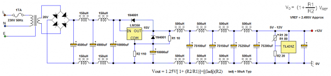
500uH won't help smoothing - to 100/120Hz it looks like a short circuit.
75100uF won't stop RF, as it will have too much inductance.
So your filter will be poor across the spectrum - the opposite of what you expected? I suggest some more reading, and building/debugging something simple.
75100uF won't stop RF, as it will have too much inductance.
So your filter will be poor across the spectrum - the opposite of what you expected? I suggest some more reading, and building/debugging something simple.
- Status
- Not open for further replies.
- Home
- Amplifiers
- Power Supplies
- LC Low Pass Filter Design.