post18
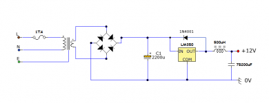
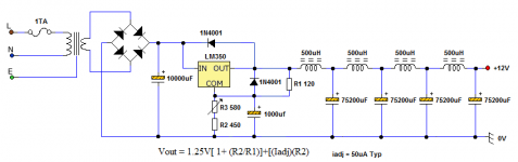
remove the 4 capacitors across the Bridge rectifier.
This is more likely to increase the chance of ripple/ringing on the output.
Try without. If there is some ringing then add a snubber (R+C) across the transformer secondary, i.e. across ~~.
1A Mains fuse is quite high.
A T1A will supply upto 230VA transformer.
You may need to add HF decoupling across the input of the reg and also across the output of the reg. What does the datasheet say?
I have removed the capacitors from the rectifier. I had never intended to use this schematic, I had just posted that one to show an example of the output LC filter. I had planned to use a completely different design entirely. I plan to add both an inline and passive, common mode and differential filter for the AC input to prevent any RF coming in through the mains.
Marce: I would prefer a linear supply to keep noise to a minimum, there is plenty of board space so it won't be a problem.
Attachments
Last edited:
You may need to add HF decoupling across the input of the reg and also across the output of the reg. What does the datasheet say?
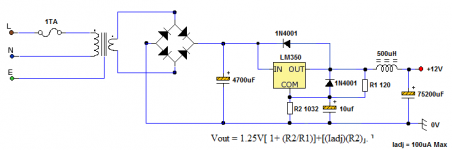
I have had a look over the datasheet, and I have reconfigured the schematic accordingly. Could someone double check the math please. If my calculations are correct, the value of R2 should give me 12V at the output (approximately).
Attachments
Last edited:
You include the Iadj current in the equation however with 1032 and 120 the math gives 12V with zero Iadj. Typically the Iadj is 50uA so you'll get around 50mV over 12V at your output. It therefore follows that your 1032 is about 5 ohms too high, it should be 1027.
R2 and the current from the OUT and ADJ pins creates a voltage that is almost perfectly a constant voltage.
You can replace R2 with a voltage reference.
A string of red LEDs looks really nice.
You can mix the diode types to get a bit of temperature compensation.
LEDs are far lower noise than a tl431, which could also be used.
BTW.
change the 1027r to 1100r. Add a 20k trim pot across it.
Now you can trim the output voltage as close as you want.
This allows you to remove the errors due to component tolerances.
If tolerance is not important, just use 1k0.
Thanks for the advice guys.
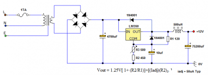
I have added a variable resistor in series with a set value resistor to allow fine tuning of the output voltage. However I had to take into account that I will want to have the option of setting the voltage to 6V, so I recalculated the resistor values. I should now be able to set the output anywhere between 6V and 12V.
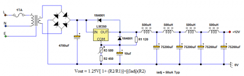
Just one more question. The output filter has an estimated cut off frequency of around 20Hz, would it be possible to lower that to 10Hz and would it take a lot of extra devices to achieve it?
Ideally, I would want the cut off frequency at 0.1Hz, but I have to take into account how practical that would be in terms of board space. The space I have available for the LC filter itself is approximately 250x80x300ml. WxHxD
I have added a variable resistor in series with a set value resistor to allow fine tuning of the output voltage. However I had to take into account that I will want to have the option of setting the voltage to 6V, so I recalculated the resistor values. I should now be able to set the output anywhere between 6V and 12V.
Just one more question. The output filter has an estimated cut off frequency of around 20Hz, would it be possible to lower that to 10Hz and would it take a lot of extra devices to achieve it?
Ideally, I would want the cut off frequency at 0.1Hz, but I have to take into account how practical that would be in terms of board space. The space I have available for the LC filter itself is approximately 250x80x300ml. WxHxD
Attachments
Last edited:
Putting two chokes in series (equivalent to 1mH) and doubling up the number of caps would reduce the turnover freq to 10Hz or so. Doubling once again (4 chokes, 64 caps) would get you to 5Hz.
Putting two chokes in series (equivalent to 1mH) and doubling up the number of caps would reduce the turnover freq to 10Hz or so. Doubling once again (4 chokes, 64 caps) would get you to 5Hz.
What I will do.
When it comes time to build the filter, I will see how much space one choke takes up. If it appears that there would be room for another one, I will add another.
I had thought about adding in some ceramic and tantalum caps for their high frequency performance, but that may not be possible if I am adding these additional chokes. I may have to stay with high value electrolytic caps to save as much space as possible.
Thanks abraxalito
This is the final schematic. I will look into making the device bigger to allow for more filter stages to bring the cut off frequency down to 5Hz.
The chassis of the device will be star connected back to earth, as the earth connection from the power cable will be connected to an AC inline choke. I will put in a large heat sink for the regulator, and use a metal plate to isolate the filter stages from the main transformer of the power supply.
If anyone can suggest additional methods to reduce noise and RFI, it would be appreciated.
Thanks
Attachments
You've not yet taken up my suggestion to implement LCLC filtering prior to the regulator. Also a bigger bypass cap than 10uF is recommended.
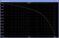
I ran a quick sim and with the 4 section LC filter on the output the response is overdamped,(due to the choke's ESR) meaning there's no well defined corner frequency. This probably isn't a problem in practice as with a power supply noise filter such as this there's no requirement to have a flat passband.
Adding extra caps for better RF rejection probably won't have any effect as even audio band rejection is going to be more layout dependent than anything else. My sim shows almost 140dB rejection at 200Hz which will only be approached with very careful grounding practices.
You've not yet taken up my suggestion to implement LCLC filtering prior to the regulator. Also a bigger bypass cap than 10uF is recommended.
I ran a quick sim and with the 4 section LC filter on the output the response is overdamped,(due to the choke's ESR) meaning there's no well defined corner frequency. This probably isn't a problem in practice as with a power supply noise filter such as this there's no requirement to have a flat passband.
Adding extra caps for better RF rejection probably won't have any effect as even audio band rejection is going to be more layout dependent than anything else. My sim shows almost 140dB rejection at 200Hz which will only be approached with very careful grounding practices.
I would put in another LCLC filter prior to the regulator, but I am not sure there will be enough space left, considering that there will be 4 LC filters on the output stage. I might need an enclosure the size of a suitcase if I put in any more LC filter stages. What do you reckon?
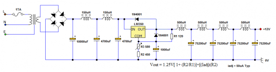
For now, I have replaced the 10uF bypass capacitor with 1000uF, and replaced the 4700uF capacitor between the rectifier and the regulator with a solid 10,000uF.
Attachments
I think if space is running low it'd be better to sacrifice one of the output LCs in favour of an LC stage on the input. But the input LC stage will be smaller as it certainly doesn't need to aim for a 20Hz turnover freq. I reckon something like 150uH 4700uF 150uH 4700uF beyond the 2200uF you had already included would make the reg's job easier. The 150uH inductors will only be 2.5cm across if Sendust so hardly suitcase sized.
I think if space is running low it'd be better to sacrifice one of the output LCs in favour of an LC stage on the input. But the input LC stage will be smaller as it certainly doesn't need to aim for a 20Hz turnover freq. I reckon something like 150uH 4700uF 150uH 4700uF beyond the 2200uF you had already included would make the reg's job easier. The 150uH inductors will only be 2.5cm across if Sendust so hardly suitcase sized.
Okay, I have added in the additional LC stages prior to the regulator. I just kept that 10,000uF capacitor there, as it won't do any harm.
I'll need to make a point of keeping the inductors well clear of each other inside the enclosure. I worked out a way to make a grid network for each LC stage of capacitance, as stay efficient with space.
Will the LC filters definitely be able to remove all frequencies from 5Hz and up? because I had read that electrolytic caps were not suitable for really high frequencies and that another type of capacitor would be required, such as Ceramic and Tantalum. Does that still apply with an LC filter?
Attachments
Will the LC filters definitely be able to remove all frequencies from 5Hz and up? because I had read that electrolytic caps were not suitable for really high frequencies and that another type of capacitor would be required, such as Ceramic and Tantalum. Does that still apply with an LC filter?
I'm attaching the plot of how the 4 LC stages look, attenuation wise. Note almost 100dB attenuation by 100Hz. At 5Hz, about 10dB attenuation.
Its true electrolytics turn inductive in the 10's of kHz usually so aren't much good above a few hundred kHz. But here since the attenuation above 100Hz is limited by layout issues, not component limitations, ceramics are going to be a complete waste of time.
Attachments
How about placing inductors in the ground rail.
I think I will mirror the inductors on the ground rail also, just to keep it balanced.
I'm attaching the plot of how the 4 LC stages look, attenuation wise. Note almost 100dB attenuation by 100Hz. At 5Hz, about 10dB attenuation.
Its true electrolytics turn inductive in the 10's of kHz usually so aren't much good above a few hundred kHz. But here since the attenuation above 100Hz is limited by layout issues, not component limitations, ceramics are going to be a complete waste of time.
I want to be sure that RFI is kept to a minimum level, that includes anything from 3Khz up to the 300Ghz. Twisted pair internal and external wiring along with Ferrite beads will only achieve so much. Is there anything else I could consider?
Last edited:
In order to reject infrared radiation, you will need optical components rather than electronic ones.I want to be sure that RFI is kept to a minimum level, that includes anything from 3Khz up to the 3000Ghz. Twisted pair internal and external wiring along with Ferrite beads will only achieve so much. Is there anything else I could consider?
In order to reject infrared radiation, you will need optical components rather than electronic ones.
I meant 300Ghz. I corrected the post.
The power supply will be used for powering various digital devices, so RFI must be kept to a minimum.
The enclosure of the chassis will be star connected back to earth for additional protection from external sources of RFI, but I am interested in additional circuit techniques to attenuate RFI.
Last edited:
- Status
- Not open for further replies.
- Home
- Amplifiers
- Power Supplies
- LC Low Pass Filter Design.