Use of Type Tip transistor as driver and output ,even with single supply works good,use schooty,If you use faster not nesseray you should use 47 pf from base to collector on
driver stage,ot critical,other transistor not matvhed but input,you trim output offset with
100 k trim resistor under 50 mv easy.
diod in bridge and 10000 uf and up are ,only necessery
driver stage,ot critical,other transistor not matvhed but input,you trim output offset with
100 k trim resistor under 50 mv easy.
diod in bridge and 10000 uf and up are ,only necessery
The End mk.II test
Most important listening test by 10 different audio people based on
the DC-amplifier: ”The End mk.II”
1990:
1) TIP35/TIP36 Ft: 3mHz +- 45VDC 1 x 500W single supply 20.000uF/63V 1 bridge: Overall reasonable good sound, little harsh tweeter, midrange a little compressed, heavy bottom which could have more difinition.
1993:
2) MJ802/MJ4502 Ft: 2mHz +- 43VDC 2 x 500W double supply, 2 x 45.000uF/63V( Maron 15.000uF x 3) + 10uF polyprop. Each, 4 bridges , safe protection 4 double 10A goldcontact relays : Very good sound, no harsh high frequence sound, very strong significant, tight low frequence reproduction. Running at 90% power music for 10 hours completely stable. Superlarge heatsinks.
1993:
3) MJ15003/MJ15004 Ft: 2mHz +- 55VDC 1 x 625W single supply 15.000/80V Nippon Chemicon, 2 x bridges, 4,7uF polyprop, safe protection 2 double 10A goldcontact relays: Excellent bass driver, great soundstage, wish for more high frequnce details and definition.
1995:
4) MJL3281A/MJL1302A MOT. Ft: 30mHz +- 56VDC 2 x 500W E-transformers ,double supply 2 x 47.000uF/80V Hitachi ( 1 x 47.000uF like large beercan), 10uF Wima 250V MKP10, 4 x 35A bridges, safe protection 4 x 10A Omron goldcontact relays: Excellent tweeter responce with fine definition, great soundstage with a lot of midrange details, superfast authoritative very deep bass responce. The best setup at this point.
1997:
5) 2SC3281/2SA1302 Toshiba Ft: 30mHz +- 52VDC 1 x 1000W single supply 47.000uF/80V Hitachi, 10uF MKC 400V polycarbonate, 2 x 35A bridges, safe protection 2 x 10A goldcontacts trible point 48VDC Matushita relays:
Very musical amplifier, excellent high range reproduction without highhat spikes, well defined midrange, and absolutely no loss at low frequences, may be not quite so fast in the bass region as the 1995 MJL Motorola amplifier.
2002:
6)2SC5200/2SA1943 Toshiba Ft: 30mHz +- 51VDC 2 x 500W double supply , 2 x 50.000uF/63V Nippon low ESR ( 10.000uF x 5) 10uF polyprop Wima MKP10, 4 x 35A bridges+ 4 x 10n, safe protection 4 x 10A double goldcontact double points Erni relays, large heatsinks 32cm wide x 16cm high x 5cm deep :
May be the most detailed high frequence definition so far, excellent midrange with very accurate determination of the location of instruments, deep very powerful significant bass reproduction.
Until now may be the most musical and best sounding amplifier based on ”The End mk.II” circuit.
2015:
7) 2SC3284/2SA1303 LAPT Silicon Epitaxial Planar Transistor , Sanken Ft: 50mHz , amplifier not ready yet!
Other transistors tested with ”The End mk.II” circuit:
2N3773/2N6609 , 2SD555/2SB600, MJ15025/MJ15024, MJ21196/MJ21195, a.m.others
LC mk2 also good with slower transistors even TO-3 type with 4 mhz type,not critical
very dynamic with easy driven speakers,but from 8-4 ohm recomend minimum last.
i use Dynaudio are 4 ohm works relative good,with Von Sweikert are excellent smaller
model speakers bookstand.
very dynamic with easy driven speakers,but from 8-4 ohm recomend minimum last.
i use Dynaudio are 4 ohm works relative good,with Von Sweikert are excellent smaller
model speakers bookstand.
Another i think are interesting to use of Toshiba ring emitter transistos for experiment
as output power transistor, no feedback and power supply are important,the original recomend two bridges and also separate supply for example 2*30-33 AC trafo, and RC coupled with two 10000 uf with 1 ohm resistor in series to next condensator on plus and resp negative pol, fun to it's works down to 15 volt DC as low level listening also.
as output power transistor, no feedback and power supply are important,the original recomend two bridges and also separate supply for example 2*30-33 AC trafo, and RC coupled with two 10000 uf with 1 ohm resistor in series to next condensator on plus and resp negative pol, fun to it's works down to 15 volt DC as low level listening also.
For millenium recomend separate lower power transformer 30 VA same voltage as
output stage for input card,can use even with LC mk2 also good i think are best.
output stage for input card,can use even with LC mk2 also good i think are best.
IT' s cleaner sound with Schooty diod bridges power, i use RIFA but Panasonic are good too.
Please: Schottky diode.
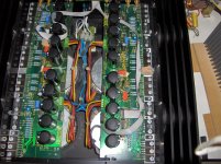
A photo of a later LC Audio amplifier: my LC Patriot V 100.
Attachments
Patriot?
Don't know "LC Patriot" ...nice photo....how many output's? ...looks like 4?
Could you post the "Patriot" schematic?
Gudmund
A photo of a later LC Audio amplifier: my LC Patriot V 100.
Don't know "LC Patriot" ...nice photo....how many output's? ...looks like 4?
Could you post the "Patriot" schematic?
Gudmund
Another i think are interesting to use of Toshiba ring emitter transistos for experiment
as output power transistor, no feedback and power supply are important,the original recomend two bridges and also separate supply for example 2*30-33 AC trafo, and RC coupled with two 10000 uf with 1 ohm resistor in series to next condensator on plus and resp negative pol, fun to it's works down to 15 volt DC as low level listening also.
Yes...the LAPT output transistors is used in "The End mk.3.1", 2SC2922/2SA1216......
.....we have tried the mk.3.1 version at different voltages , with and without servo.....it seems that the sound from the mk.3.1 is getting closer to a standard high quality factory made superamp.....
.....after many experiments the general assessment or evaluation among the 10 audiophiles was, that the simplicity by the mk.II circuit distinguishes itself by not adding the music signal unwanted sound supplements at the different frequencies.
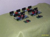
The mk.3.1 attached
We would like to try the LAPT Sanken together with the "mk.II" version....
.... link "mk.3.1" in #58
Attachments
Last edited:
Yes...the LAPT output transistors is used in "The End mk.3.1", 2SC2922/2SA1216......
.....we have tried the mk.3.1 version at different voltages , with and without servo.....it seems that the sound from the mk.3.1 is getting closer to a standard high quality factory made superamp.....
.....after many experiments the general assessment or evaluation among the 10 audiophiles was, that the simplicity by the mk.II circuit distinguishes itself by not adding the music signal unwanted sound supplements at the different frequencies.
The mk.3.1 attached
We would like to try the LAPT Sanken together with the "mk.II" version....
.... link "mk.3.1" in #58
I Would love to hear the result from mk.ii with sanken☺
The End mk.3.1 Copyright?
We do not know if there are still copyright on the two circuits "The End mk.3.1", 1995 and "The End Millennium XP", 2000.
As I read it on this website: "LC Audio Technology", owns the two circuits, and the company has given permission to display them here:
https://sites.google.com/site/httpstubeamp/home
Halfway on the page, you will find links to both Google.docs and Picasaweb where there is a description and a component guidance.
The "mk.3.1" circuit is shown without the servo. The "XP" is shown with servo.
"The End Millennium XP" with SMD components and on-board servo does not sound like "The End mk.3.1" and certainly not like "The End mk.II"
Rgds.
Hi Gudmund,
Can you show schematics of MK3.1 version.
I'm very interested.
Thanks,
Regard.
We do not know if there are still copyright on the two circuits "The End mk.3.1", 1995 and "The End Millennium XP", 2000.
As I read it on this website: "LC Audio Technology", owns the two circuits, and the company has given permission to display them here:
https://sites.google.com/site/httpstubeamp/home
Halfway on the page, you will find links to both Google.docs and Picasaweb where there is a description and a component guidance.
The "mk.3.1" circuit is shown without the servo. The "XP" is shown with servo.
"The End Millennium XP" with SMD components and on-board servo does not sound like "The End mk.3.1" and certainly not like "The End mk.II"
Rgds.
Sanken 2SC3284/2SA1303 LAPT
We try with the "smaller" Sanken LAPT 2SC3284/ 2SA1303 , TO3P, 150V, 50mHz.
... ordered 100 .
300 of 2SC2240/2SA970 Toshiba GR,
200 of BC560C/BC550C Motorola , Motorola very similar basic transistors
50 pcs of 10.000uf/63V Nippon Chemicon Low ESR
100 pcs of 3.900/80V Nippon Chemicon Low ESR... fast
Wima MKP10.....many.
A lot of hobby work ahead ............
I Would love to hear the result from mk.ii with sanken☺
We try with the "smaller" Sanken LAPT 2SC3284/ 2SA1303 , TO3P, 150V, 50mHz.
... ordered 100 .
300 of 2SC2240/2SA970 Toshiba GR,
200 of BC560C/BC550C Motorola , Motorola very similar basic transistors
50 pcs of 10.000uf/63V Nippon Chemicon Low ESR
100 pcs of 3.900/80V Nippon Chemicon Low ESR... fast
Wima MKP10.....many.
A lot of hobby work ahead ............
Most important listening test by 10 different audio people based on
the DC-amplifier: ”The End mk.II”
1990:
1) TIP35/TIP36 Ft: 3mHz +- 45VDC 1 x 500W single supply 20.000uF/63V 1 bridge: Overall reasonable good sound, little harsh tweeter, midrange a little compressed, heavy bottom which could have more difinition.
1993:
2) MJ802/MJ4502 Ft: 2mHz +- 43VDC 2 x 500W double supply, 2 x 45.000uF/63V( Maron 15.000uF x 3) + 10uF polyprop. Each, 4 bridges , safe protection 4 double 10A goldcontact relays : Very good sound, no harsh high frequence sound, very strong significant, tight low frequence reproduction. Running at 90% power music for 10 hours completely stable. Superlarge heatsinks.
1993:
3) MJ15003/MJ15004 Ft: 2mHz +- 55VDC 1 x 625W single supply 15.000/80V Nippon Chemicon, 2 x bridges, 4,7uF polyprop, safe protection 2 double 10A goldcontact relays: Excellent bass driver, great soundstage, wish for more high frequnce details and definition.
1995:
4) MJL3281A/MJL1302A MOT. Ft: 30mHz +- 56VDC 2 x 500W E-transformers ,double supply 2 x 47.000uF/80V Hitachi ( 1 x 47.000uF like large beercan), 10uF Wima 250V MKP10, 4 x 35A bridges, safe protection 4 x 10A Omron goldcontact relays: Excellent tweeter responce with fine definition, great soundstage with a lot of midrange details, superfast authoritative very deep bass responce. The best setup at this point.
1997:
5) 2SC3281/2SA1302 Toshiba Ft: 30mHz +- 52VDC 1 x 1000W single supply 47.000uF/80V Hitachi, 10uF MKC 400V polycarbonate, 2 x 35A bridges, safe protection 2 x 10A goldcontacts trible point 48VDC Matushita relays:
Very musical amplifier, excellent high range reproduction without highhat spikes, well defined midrange, and absolutely no loss at low frequences, may be not quite so fast in the bass region as the 1995 MJL Motorola amplifier.
2002:
6)2SC5200/2SA1943 Toshiba Ft: 30mHz +- 51VDC 2 x 500W double supply , 2 x 50.000uF/63V Nippon low ESR ( 10.000uF x 5) 10uF polyprop Wima MKP10, 4 x 35A bridges+ 4 x 10n, safe protection 4 x 10A double goldcontact double points Erni relays, large heatsinks 32cm wide x 16cm high x 5cm deep :
May be the most detailed high frequence definition so far, excellent midrange with very accurate determination of the location of instruments, deep very powerful significant bass reproduction.
Until now may be the most musical and best sounding amplifier based on ”The End mk.II” circuit.
2015:
7) 2SC3284/2SA1303 LAPT Silicon Epitaxial Planar Transistor , Sanken Ft: 50mHz , amplifier not ready yet!
Other transistors tested with ”The End mk.II” circuit:
2N3773/2N6609 , 2SD555/2SB600, MJ15025/MJ15024, MJ21196/MJ21195, a.m.others
Very interesting report of this listening test - thank you therefore. Interesting to know it would be for me, whether the reason for the harsh upper frequency range and the little compressed midrange at the first version from 1990 was mainly the power output devices from TI (TIP-Series) or the electrolytics from the power supply.
"The End mk.I" 1989
The first version of "The End" (1989) was introduced with a input stage, where the input impedance was very low.
In the same "Mk.I" version L.H. Clausen used the old Motorola small signal transistors BC449 / BC450. They were on their limit due to the relatively high operating voltage.
The slightly sharp tweeter responce and the undefinable bass reproduction, was not caused by the Texas TIP35 / TIP36 output transistors or the excellent Philips 10.000uf / 63V (4 pcs) capacitors.
The explanation for the slightly strained sound lay in the input stage and the old Motorola small signal transistors. The BC transistors were at the limit of their performance.
The original "The End" design was good, but was adjusted into place in the Mk.II version. The input impedance was raised to approx. 22K, and the small signal transistors were replaced with the good Toshiba 2SC2240 / 2SA970.
The TIP35C / TIP36C sounded reasonable, but it soon turned out, that the sound reproduction was improved considerably by better output transistors.
You can find the old diagram of "The End Mk.I" on the mentioned website
Very interesting report of this listening test - thank you therefore. Interesting to know it would be for me, whether the reason for the harsh upper frequency range and the little compressed midrange at the first version from 1990 was mainly the power output devices from TI (TIP-Series) or the electrolytics from the power supply.
The first version of "The End" (1989) was introduced with a input stage, where the input impedance was very low.
In the same "Mk.I" version L.H. Clausen used the old Motorola small signal transistors BC449 / BC450. They were on their limit due to the relatively high operating voltage.
The slightly sharp tweeter responce and the undefinable bass reproduction, was not caused by the Texas TIP35 / TIP36 output transistors or the excellent Philips 10.000uf / 63V (4 pcs) capacitors.
The explanation for the slightly strained sound lay in the input stage and the old Motorola small signal transistors. The BC transistors were at the limit of their performance.
The original "The End" design was good, but was adjusted into place in the Mk.II version. The input impedance was raised to approx. 22K, and the small signal transistors were replaced with the good Toshiba 2SC2240 / 2SA970.
The TIP35C / TIP36C sounded reasonable, but it soon turned out, that the sound reproduction was improved considerably by better output transistors.
You can find the old diagram of "The End Mk.I" on the mentioned website
Thanks Gudmund for your answer.
What the version which have the best sounding you was hear?!
Regard,
Walkalone.
What the version which have the best sounding you was hear?!
Regard,
Walkalone.
mk.II vs mk.3.1
Very difficult question because it depends on the build quality.
With emphasizing....if you follow the guidelines as mentioned before .....I would prefer the mk.II version.
The mk.3.1 version is much easier to build, if you don't have access to match all transistors.
If you choose the mk.II remember... do not use cyanacrylate or two component epoxy glue on the small-signal transistors as many has done ... ...use small cable ties in plastic. It is essential to keep the small signal transistors in stable heat-balance.
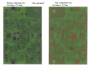
Another parameter is the PCB size and the size/orientation of the cobber lines....the attached PCB size delivers the best high frequence performance.
A scan of the mk.II PCB's attached..... find the drawing and component values here:
Picasa Web Albums - vbkolsen - The End MKII ...
I do not have gerber-files for the attached mk.II PCB nor the mk.3.1!
Thanks Gudmund for your answer.
What the version which have the best sounding you was hear?!
Regard,
Walkalone.
Very difficult question because it depends on the build quality.
With emphasizing....if you follow the guidelines as mentioned before .....I would prefer the mk.II version.
The mk.3.1 version is much easier to build, if you don't have access to match all transistors.
If you choose the mk.II remember... do not use cyanacrylate or two component epoxy glue on the small-signal transistors as many has done ... ...use small cable ties in plastic. It is essential to keep the small signal transistors in stable heat-balance.
Another parameter is the PCB size and the size/orientation of the cobber lines....the attached PCB size delivers the best high frequence performance.
A scan of the mk.II PCB's attached..... find the drawing and component values here:
Picasa Web Albums - vbkolsen - The End MKII ...
I do not have gerber-files for the attached mk.II PCB nor the mk.3.1!
Attachments
Last edited:
- Status
- Not open for further replies.
- Home
- Amplifiers
- Solid State
- LC audio The End