To Fred:
It was published in a swedish magazine "High Fidelity" 1989.
There was no payment to Lars from readers to use the schmatics and build the amp.
I Don't remember about the PCB price?
Any service/Help from Lars here, I feel is welcome since the design has moved on since the first version. There is no need to be upset.
IMHO
\Jens
EDIT: Written before I saw Peters post
Dear Lars,
Would you consider scanning and posting the PCB on The End 2 also. It seems that it would be very interesting to analyse...
I have The End Millennium as my main amp at the moment and I'm quite happy with it. And the history of the current implementation is always interesting.
Regards,
Ergo
Would you consider scanning and posting the PCB on The End 2 also. It seems that it would be very interesting to analyse...
I have The End Millennium as my main amp at the moment and I'm quite happy with it. And the history of the current implementation is always interesting.
Regards,
Ergo
I am not playin scrabble and I am not an EE but it seems to me that transistors have certain specs and are not inherently doing anything. It's up to the designer to insure that an adequate margins of safety are built in the circuit to avoid instabilities. Blaming it on the poor transistor seems like blaming the steering wheel for having taken the car off the road instead of the driver or the poor way in which the car was designed.
I'm even more confused..........
I have been making open-loop amplifiers for 10, maybe 12 years now without stability problems. Unlike all the amps that I built previously which did have stability problems.
In any case, the last thing that I would use in a power amp is a TIP-anything. YUK!!!
If a "fast" transistor is causing problems, then there are serious issues that should be dealt with, before blaming the transistor.
No more free design help..........you are on your own here.
Jocko
I build two of these when I was 17 (eg. not very thorough... you know, teenagers...), and they both worked on the first try. The design was quite popular at the time and I now of several others who also got it to work quite easily, so I wouldn't blame the design in it self.
It does have one curiosity though. The input ground is NOT connected to the power ground on the PCB (at least not on the mk2) and if you don't connect it properly to ground (at the input terminals, I think is the best place, just use the shield of a shielded cable) the amp WILL oscillate and burn the outputs. I know that 😡 Could your problem lay here?
About the transistors, I upgraded one to use 2sa1606 drivers and 2sa1386 outputs (and compl. npn), both of which are pretty fast. It worked like a charm (I wouldn't claim to be able to hear any difference though...) I put a 100p capacitor over the drivers as recommended somewhere, and the PCB for mk2 has added base resitors on the outputs (22ohm I think). This seems to be enough to keep everything nice and stable.
Good luck
Joachim
Mean Jocko!
Jocko,
This is where you get your free stuff.......................😀
http://www.free-stuff.com/
Jam
Jocko,
This is where you get your free stuff.......................😀
http://www.free-stuff.com/
Jam
Re: I'm even more confused..........
Aren't both Fred and Jocko really negative here? Has Fred and Jocko listened to The End? Can't you guys try to be a little bit positive? I don't either get good vibes when I hear TIP something but this more a feeling than a fact.Jocko Homo said:In any case, the last thing that I would use in a power amp is a TIP-anything. YUK!!!
No more free design help..........you are on your own here.
Some years ago I have built a amp (Volksintegrated , project by Luca Comi, published on the Italian magazine costruire Hi-Fi) that uses TIP41 and 42C as outputs, and despite they are considered "rubbish" transistors this amp easily blew away a Yamaha of about the same power.
I think that in some topologies these transistors can perform quite well, in others are hopeless.
After all, there are legendary amps which use the 2N3055...
Of course now there are much better choiches, but keep in mind that this design is about 15 years old...
Cheers
Andrea
I think that in some topologies these transistors can perform quite well, in others are hopeless.
After all, there are legendary amps which use the 2N3055...
Of course now there are much better choiches, but keep in mind that this design is about 15 years old...
Cheers
Andrea
Upside down, inside out...
I have another curiosity question that Lars or some of the Gurus (no names mentioned 🙄 ) might be able to comment on.
If you look at the schematic linked in Lars' earlier post, you will see that The End mk2 has the collectors of the output transistors connected to the output terminal and the emmiters to the rails. Most other amps (including The End XP) have their output stages the other way around, e.g. the transistors are connected as emitter followers.
What are the advantages/disadvantages of each of these topologies?
/Joachim
ps: I'm not seeking free advice, I'm just curious... (but is this forum anything but free advice anyway ?)
Andrea,
don't forget the eta beta of B. Aloia, circa 1985, ancient history. 😉
As I recall BA is still using the topology in his 13.XX line but Japanese transistors.
don't forget the eta beta of B. Aloia, circa 1985, ancient history. 😉
As I recall BA is still using the topology in his 13.XX line but Japanese transistors.
Re: Upside down, inside out...
To see how it works consider what t15 does if you try to pull the emitter of t13 low (MK11 diagram). The collector of t15 will begin sourcing current in an attempt to pull t13 emitter back up again.
This arrangement is called a Complementary Feedback Pair and is supposedly more linear that an emitter follower because the output is within a local negative feedback loop.Joachim_b said:If you look at the schematic linked in Lars' earlier post, you will see that The End mk2 has the collectors of the output transistors connected to the output terminal and the emmiters to the rails. Most other amps (including The End XP) have their output stages the other way around, e.g. the transistors are connected as emitter followers.
What are the advantages/disadvantages of each of these topologies?
To see how it works consider what t15 does if you try to pull the emitter of t13 low (MK11 diagram). The collector of t15 will begin sourcing current in an attempt to pull t13 emitter back up again.
Thank you all for very helpfull replies!
As soon as possible I will try out a cap connected to PG-heatsink
and starground connection in cabinet and yes, I will change every transistor.
Jazzpeter: A picture would be great (or anyone elses "The End" project). Always fun to see other solutions (probably every DIY constructors nightmare)
/Jan
As soon as possible I will try out a cap connected to PG-heatsink
and starground connection in cabinet and yes, I will change every transistor.
Jazzpeter: A picture would be great (or anyone elses "The End" project). Always fun to see other solutions (probably every DIY constructors nightmare)
/Jan
Grataku: I'm not blaming the 2SA968 / 2SC2238 pair, it's a great pair, however if the circuit is designed for types with different properties, then the user can not expect the design to be stable when using this pair.
It is like if you have a Porsche and you fit bicycle wheels on it, and expect it to drive perfectly with those. The Porshe is good, the bicycle wheels are good, but they are just not good together. If the Porsche was designed for use with bicycle wheels, then everything would be ok. Forgive my reuse of the car analogy 😉
What i mean with the above transistor pair's inherent instability is that they will oscillate if connected in most common audio circuits, if no special care is taken to prevent it. They have a very low Cbc, actually higher than Cbe. When connected in a circuit with just a minimum of capacitive load on the emitters, you effectively have a Colpitts oscillator circuit.
Richard C : Right on, the feedback loop reduces the distorsion of the low cost TIP devices to an acceptable performance. However we wanted to remove even the last feedback loop in The End amplifiers, and therefore switched to the more linear SANKEN output devices. They allowed us to remove that feedback loop back in 1995, and have a design alltogether free from feedback loops.
Just to correct a small misunderstanding, The End was published in both a danish and the swedish version of the same magazine in 1989, and the mk 2 version in 1990. I never sold PCB's for this amplifier, but a company in Copenhagen did. I did not make money of this project at all, but only saw it as fun to get something i made as a hobby published in a magazine. However the amplifier got so much succes that the Mk 3 version made it possible to go from hobbyist to a small business (with my self as the only employee) in 1994.
Today almost 10 years later this company still exist, but it is not one of the commercial mastodonts of the audio business. We are totally 4 employees, one tech support guy to help people over the phone, one production worker, Vivi our pack and send girl, and my self. Basically a guy lucky enough to work with his hobby, like you could all do if you want. The main driving power is hifi and technology, nothing else, there are no pure business people involved in the company at all.
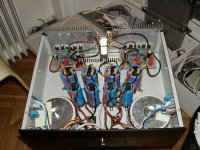
Pivture of "The End"
I promised to post a picture of my "The End" project. Here it is.
As said before, I sounded really warm and detailed before I did something silly and blew one side.....
Now I'm changing all transistors and will - hopefully - be able to listen to it again very soon.
Yes, it sound good - even with the "crappy" TIP35/36. I guess the designer must have done somthing right.....😉
More that 1800 diy-amps were built 15 years ago...
Attachments
Connection to star ground for the low level input?
Hi,
Just briefly looking at the image i do not see any connection from the star ground to the RCA. Is it done on the PCB? If not then do it, that is why i buned my amp(s).
I found out that something was wrong when i discovered 80v AC over the capacitors on the powersupply when i touched the RCA ground. The AMP was powered by +35 -35
I would like to show you pictures of my amp but it is not in a presentable shape.
Regards
Hjelm
Nice amp!
Wish I had the money to have double psu when I build mine.
Where is the starground? Can't see it on the picture.
Wish I had the money to have double psu when I build mine.
Where is the starground? Can't see it on the picture.
The End
I don't see any protection circuity for the output on the picture of completed amp - if any output transistor will go to the " silicon heaven ", it will be realy " The End ", but for in this time connected speakers . Maybe you have enough money for buying new one, but you get frightened realy much. Remember that all what is doing by man's hand, can't be absolutely reliable.
I don't see any protection circuity for the output on the picture of completed amp - if any output transistor will go to the " silicon heaven ", it will be realy " The End ", but for in this time connected speakers
. Maybe you have enough money for buying new one, but you get frightened realy much. Remember that all what is doing by man's hand, can't be absolutely reliable.The beginning of The End.....
At last I got it together.
After changing all burned transistors and doing a few other tricks I have plenty of good music comming from my "no-feedback" amp "The End".
Thanx to Lars (LCaudio) for his kind advice. Just what I needed 😀 .
Blowing a bunch of transistors learned my something about proper grounding and decoupling. I guess that it has been worth the trouble.
I established starground and let a wire go from input-ground via a 2,2ohm resistor to starground.
Then I decoupled the heathsink by a 100n MKT cap going to output ground. That nailed it. It just 100% stable now. Nice 🙂 .
Sound is warm and detailed. Actually listening to Mahlers Symphonie No.3 gave me a feeling of "Why don't I go to hear a REAL concert?"
Isn't that the essence of High-End? I mean after all - the real "highs" are the ones you get sitting infront of 40 guys doing what they are best at......😉
So far...I'm happy!
- Status
- Not open for further replies.
- Home
- Amplifiers
- Solid State
- LC audio The End