This is wonderful!After a long moment of reflection I´ve decide to offer layouting for nothing!
The only requirement is a interesting circuit or a mature design. I will offer a lot of experience and expertise but don´t request any development, they are generally long lasting and not free of charge.
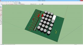
My tools are: EAGLE, SKETCHUP (with the necessary plugins).
I´m very curious about replies...
P.S.: I´m the coming week for business on the road
Congratulations!
Guys
http://www.itead.cc/open-pcb/pcb-prototyping.html
Very inexpensive pcb manufacturer. 10pcs 10*10cm for $20. $2 per board.
I have often used them. The quality is there and they are very fast.
I should also mention that you can upload the design to their "open pcb" forum and you'll get 2 free pcbs. Then anyone else can also order those boards.
JP- you're very kind for helping everyone. Thanks so much.
Last edited:
Hi Jean-Paul,
Printed it, checked it over and over, "configured" the different PS options and everything looks perfect!
many thanks 🙂
Erik
Printed it, checked it over and over, "configured" the different PS options and everything looks perfect!
many thanks 🙂
Erik
Hi Jean-Paul,
I did some read on this topic
http://www.diyaudio.com/forums/solid-state/197493-jfet-amp-current-nfb.html
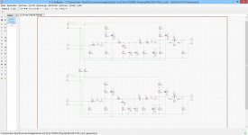
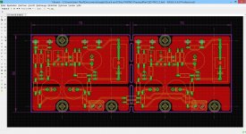
and found it is interesting. I modified the a schematic with lot of help from topic owner. Mainly to make it match my parts and plan to build it in very near future. Do you think it will worth your time to do some PCB work?
I will attach LT Schematic and one channel schematic to this post.
Thanks!
I did some read on this topic
http://www.diyaudio.com/forums/solid-state/197493-jfet-amp-current-nfb.html
and found it is interesting. I modified the a schematic with lot of help from topic owner. Mainly to make it match my parts and plan to build it in very near future. Do you think it will worth your time to do some PCB work?
I will attach LT Schematic and one channel schematic to this post.
Thanks!
Attachments


So mundorf from rail to rail but output through a KZ? I would replace expensive mundorf with something non exitic if the output is going to go through a lytic.
Hi Jean-Paul,
Can you design a PCB using the existing .png drawing of that PCB (in 1:1 scale). This is GEM amp design by Graham Maynard and I can send you the file.
Thanks,
Vlad
P.S. Here is the links to the layout:
http://www.zen22142.zen.co.uk/Circuits/Audio/gem100.htm
http://www.zen22142.zen.co.uk/Circuits/Audio/gempcblayout.png
Last edited:
Hi
could i get a strip board and normal pcb layout for this: Project 125 but with a few mods:
use the input stage in figure 1A (Linkwitz-Riley Electronic Crossover) then go to the filters. i dont need a balanced input stage.
4 way as shown
in the output buffer stages i only need one volume control and no muting switches & i also dont need a power supply as i have one to supply them but still add the 100n bypass capacitors near each opamp (TL074)
Thanks in advance
Last edited:
@obscurus
Why Mica? I use for small capacitor values WIMA FKP2 (used in the actual schematics).
Second point 2N5401 is PNP!
Regards
Jean-Paul
Why Mica? I use for small capacitor values WIMA FKP2 (used in the actual schematics).
Second point 2N5401 is PNP!
Regards
Jean-Paul
@doctormord
perhaps one day the opportunity to layout a Mr. Pass schematic for a terrific new audiophile (pleonasm?) amplifier ?
Some guys prefer to spent time for television. I´m layouting with music (Roger Waters "chef d´Oeuvre" Amused to Death).
As germans says, das liegt mir im Urin...
perhaps one day the opportunity to layout a Mr. Pass schematic for a terrific new audiophile (pleonasm?) amplifier ?
Some guys prefer to spent time for television. I´m layouting with music (Roger Waters "chef d´Oeuvre" Amused to Death).
As germans says, das liegt mir im Urin...
- Status
- Not open for further replies.
- Home
- Design & Build
- Software Tools
- Layouting for free