Hi Jean Paul,
From the opamps positive rail. I included a voltage dropping resistor + potentiometer there: I think a trimming multiturn would be good? Some decoupling of the Vref voltage could be good, I didn't include it 😱
thanks! Erik
From the opamps positive rail. I included a voltage dropping resistor + potentiometer there: I think a trimming multiturn would be good? Some decoupling of the Vref voltage could be good, I didn't include it 😱
thanks! Erik
It's an output.
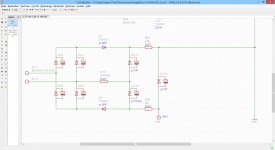
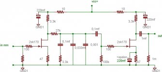
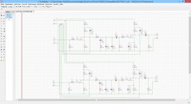
I don't geit it? V ref sets the standing current through the tubes: in the schematic it is set at 0,4V, so the servo circuit will force the cathodes to stay at 0,4V too, which, based on the 10R resistor, implies in 40mA for each tube.
Erik
Jean Paul,
I think that the regulation provided by the LM317 will be enough? Afterall, V ref is shared by all tubes, so if it changes a bit it doesn't matter, as all tubes change by the same amount. And we are dealing with output tubes and large signals, so ultimate regulation isn' necessary ( I am sure there are much "better" regulators than LM317/337 out there)
Erik
From #38 sheet 3, it "looks" like an output
Yes, indeed, or an extra input. Maybe the person that draw that schematich used an external component to set the reference voltage. Still in this case it can be derived from the Opamps PS and be shared by the four servo's, so no external connections are needed.
Erik
Hi Jean-Paul
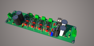
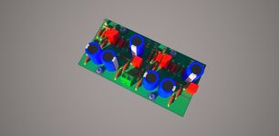
It does look very good! Thank you! Where do I order them? 🙂
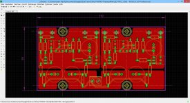
Still, I found I ommited something in my B- schematics, namely the additional RC filtering stage in the doubler and quadrupler. The bridge filter + smoothing includes the RC filtering on the left. In the doubler I can replace a jumper with a resistor do make the RC (small red circle), but in the quadrupler unfortunately not. I redraw the schematic, adding an additional RC stage (large red circle). Do you think you could add that to the PCB?
Many thanks again, best regard!
Erik
It does look very good! Thank you! Where do I order them? 🙂
Still, I found I ommited something in my B- schematics, namely the additional RC filtering stage in the doubler and quadrupler. The bridge filter + smoothing includes the RC filtering on the left. In the doubler I can replace a jumper with a resistor do make the RC (small red circle), but in the quadrupler unfortunately not. I redraw the schematic, adding an additional RC stage (large red circle). Do you think you could add that to the PCB?
Many thanks again, best regard!
Erik
Attachments

... what do you mean?
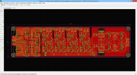
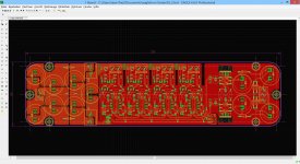
230x59mm or if both supplies on the same side 180x120mm.
Jean Paul,
I interpreted your "...what do you mean?" as "...was meinst du?", asking my opinion about the PCB layout. Or did you mean something different?
Cheers, Erik
Hello Erik,
I will check the modifications in the evening. I think it´s not a problem!
Regards,
Jean-Paul
I will check the modifications in the evening. I think it´s not a problem!
Regards,
Jean-Paul
Hi Jean Paul,
You are fast! That is indeed what I was looking for. Is it possible to have a bit larger spot for R56, to allow for a lets say 3W resistor?
You are fast! That is indeed what I was looking for. Is it possible to have a bit larger spot for R56, to allow for a lets say 3W resistor?

Hello Erik,
Ok?
I like to order my PCB´s from multi-cb.
JP
HI Jean-Paul,
thank you! And you read my mind, as I was going to ask for a PCB manufacturer 🙂
I went to Multi-cb' website Leiterplatten,PCB, SMD-Schablonen - Discount, Kurze Lieferzeit, Qualitt and went to the PCB calculator, still besides 2 layer, delivering time, board dimensions, board thickness, and quantity I could not fill in anything :O Furthermore, I saw they do not sell to private clients, bummer for me.
I do have to think about an alternative.
many thanks again! Erik
Hi Jean-Paul,
looked at JACKALTAC, these will do quite nice for me, so I will order from them! Would you like to get some of the PCB's as well (free of course)?
Erik
looked at JACKALTAC, these will do quite nice for me, so I will order from them! Would you like to get some of the PCB's as well (free of course)?
Erik
Last edited:
Hello Nick,
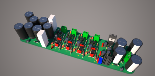
quick and dirty!
Well that was much quicker and less dirty than I would have thought 😀
If I can propose a couple of alterations:
1- Have different footprint options for the output cap (some might want to use big and bulky PIO caps or Wima MKP)
2- Have the possibility to break the board in two, making it a dual mono? this would just entail two separate power intakes that could be jumpered?
Thanks a lot!
- Status
- Not open for further replies.
- Home
- Design & Build
- Software Tools
- Layouting for free