I'd be very interested in the Gerbers etc. when you are ready tcd. Yes international is a pain - Just send some Meridian speakers to China.
I would wait until the prototype has been built before getting a boards. However if interested, i can upload the SL6 file and Gerbers and drill files which would allow you to get boards at your leisure...
Yes please, I’d be interested also.
I prefer to use connectors rather than directly soldering wires to the pcb.
[/ATTACH][/ATTACH]
Here's the Gerbers, drill file and SL6 file. They should be enough to play with.
Remember:
1. SL6 file is zipped so you need to uncompress first
2. Component numbering is as per my earlier post, not same as Minek123's.
If you don't have Sprint Layout, there is a free viewer.🙂
Here's the Gerbers, drill file and SL6 file. They should be enough to play with.
Remember:
1. SL6 file is zipped so you need to uncompress first
2. Component numbering is as per my earlier post, not same as Minek123's.
If you don't have Sprint Layout, there is a free viewer.🙂
Attachments

Tcd1963,
Thanks for posting the Gerbers.
Just curious,
-Why the decision not to through-plate all of the pads?
-Omission of unused opamp lead pads?
Thanks for posting the Gerbers.
Just curious,
-Why the decision not to through-plate all of the pads?
-Omission of unused opamp lead pads?
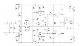
Since LatFet devices are expensive, and the only source of them is Exicon from UK (shipping takes long), here is Vertical Fet version.
Popular IRFP240/IRFP9240 devices can be used.
Or, even better: FQA27N25/FQA36P15 pair.
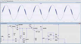
The sim here (attached) has been done for IRFP devices.
Compared with LetFet version - drivers have been added, and thermal tracking bias spreader. All the parameters are comparable to LatFet version.
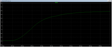
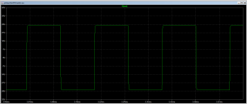
Sim has been tested for 1kHz, 10kHz, 20kHz waves, squares, and clipping, and the amp seems to behave very stable.
Slew rate seems to be in 40V/us range, which isn't bad.
For vertical fets, gate protection Zeners should be added in the actual build.
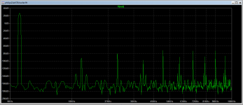
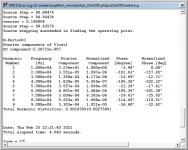
Thd and FFT screenshots attached for 1kHz and 10kHz sinus waves.
5kHz square wave + zoom to show the rise time.
Source resistors are not needed - if using just 1 pair of output devices.
Popular IRFP240/IRFP9240 devices can be used.
Or, even better: FQA27N25/FQA36P15 pair.
The sim here (attached) has been done for IRFP devices.
Compared with LetFet version - drivers have been added, and thermal tracking bias spreader. All the parameters are comparable to LatFet version.
Sim has been tested for 1kHz, 10kHz, 20kHz waves, squares, and clipping, and the amp seems to behave very stable.
Slew rate seems to be in 40V/us range, which isn't bad.
For vertical fets, gate protection Zeners should be added in the actual build.
Thd and FFT screenshots attached for 1kHz and 10kHz sinus waves.
5kHz square wave + zoom to show the rise time.
Source resistors are not needed - if using just 1 pair of output devices.
Attachments
-
philips22ah578.hexfet.asc11.4 KB · Views: 109
-
 philips22ah578.hexfet.5khz_rsq_rise.png19.7 KB · Views: 244
 -
 philips22ah578.hexfet.5khz_sqr.png19.6 KB · Views: 183
 -
 philips22ah578.hexfet.10khz_fft.png24.7 KB · Views: 208
 -
 philips22ah578.hexfet.10khz_thd.png25.6 KB · Views: 517
 -
 philips22ah578.hexfet.1khz_fft.png23.9 KB · Views: 518
 -
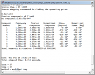 philips22ah578.hexfet.1khz_thd.png25.1 KB · Views: 583
 -
 philips22ah578.hexfet.jpg207.4 KB · Views: 599
Last edited:
LatFETs aren't particularly expensive compared to predriver+driver+output BJT though - and you have to include the thermal bias circuitry and pcb area too in the hidden costs of not using these thermally stable output devices with easy drive requirements.
My take is that lats make a lot of sense, and many classic Hitachi circuit LatFET amps are legendary as being bomb-proof, reducing the cost of ownership over time! What takes many amps out over time is either secondary breakdown or gradual bias drift, both resulting in thermal runaway. Lats are inherently robust against this.
My take is that lats make a lot of sense, and many classic Hitachi circuit LatFET amps are legendary as being bomb-proof, reducing the cost of ownership over time! What takes many amps out over time is either secondary breakdown or gradual bias drift, both resulting in thermal runaway. Lats are inherently robust against this.
LatFETs aren't particularly expensive compared to predriver+driver+output BJT though - and you have to include the thermal bias circuitry and pcb area too in the hidden costs of not using these thermally stable output devices with easy drive requirements.
Good BJT's are much easier to source though. Exicon is pretty much the only supplier of good quality lateral FETs now... whereas good outputs, drivers and predrivers can be gotten at any major parts supplier
Mark, you are right of course,
but - there is lots of builders who simply don't have LatFets in stock,
however they do have IRFPs (and BJTs for drivers) available by the bucket..
I have at least 10 pairs of IRFPs in my "failed amps trash bin", ready to be de-soldered and re-used 🙂
Also ordering LatFets from UK takes much longer these days...
I'm a big fan of Latfets, they make everything easier, but I see slightly better sim results with HExFets - not talking specifically about this amp, but in general..
Not sure if these results are truly better in real builds though..
Last edited:
It's also rather a fact that LatFETs are obsolete and disappearing from the market fast. I suspect there will always be suitable Hex/VFETs though, and even suitable BJT's for many years yet
Tcd1963,
Thanks for posting the Gerbers.
Just curious,
-Why the decision not to through-plate all of the pads?
-Omission of unused opamp lead pads?
If any rework is required, then desoldering pads on one side is a lot easier than desoldering through plated pads. I sometimes also spray the completed underside with PCB lacquer and don't particularly want to to spray the top side components.
The unused opamp lead pads waa my shortcut since space between the resistor leads and the opamp leads was very little. Perhaps better arrangement of the resistors would have helped...🙂
All the PCBs are gone.
All have been mailed today.
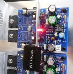
For a reference, here is a closeup of the assembled board.
As the values of the resistors/caps please refer to the schematic from the 1st post.
Some of the values printed on the silkscreen are not correct - they have been tweaked during prototyping/testing.
C15 (68pF) has been soldered under the PCB, in parallel to R3.
All have been mailed today.
For a reference, here is a closeup of the assembled board.
As the values of the resistors/caps please refer to the schematic from the 1st post.
Some of the values printed on the silkscreen are not correct - they have been tweaked during prototyping/testing.
C15 (68pF) has been soldered under the PCB, in parallel to R3.
Attachments
Last edited:
Or enable included RL output network (coil + resistor), this will also take care of these oscillations.
Do 22 Ohm gate resistors work OK with 10kHZ/20kHz sinus and squares?
If it doesn't affect them, you are right - that's better solution than counting on RL to fix it.
Do 22 Ohm gate resistors work OK with 10kHZ/20kHz sinus and squares?
If it doesn't affect them, you are right - that's better solution than counting on RL to fix it.
Yes. It's OK. I'm using 2x2,2m Van Damme Blue LS cable with 91dB 2way floorstandig speakers. I don’t usually build coils in amplifiers, unless stability issues make it necessary. BTW great design as usually.
So while ago I bought QA401 Quant Asylum audio analyzer.
Finally today, I gave it first try.
It's a complicated tool, and I guess I have a lot to learn how to properly use it.
Just few observation for now.
I tried to measure this amp (LatFet based on Phillips AH578).
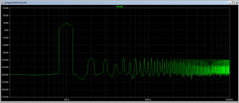
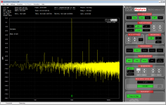
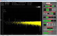
First of all I'm not sure if these measurements are worth anything since the noise floor reported by QA401 is at -100dB (with amp OFF).
Kind of high. The examples from QA user guide show noise floor at -140dB.
Simmed FFT profile for this amp is well below -100dB.
So most likely most of the information we want to see is below noise level.
Anyway, I tried to test.
Gain reported: 28dB
"Thd + noise floor" never goes above 0.04%, even for 20kHz signal.
Just "Thd" is usually lower.
So if these results are correct, that's not too bad..
Strange thing - the higher the frequency, Thd seems to go down a bit.
FFT profile measured/shown is pretty much indstinguishable from 'noise floor' with exception of harmonics showing spikes, which looks more or less normal.
So far I didn't go over 40W of power - not sure if my dummy load I built for this test can take more than 40W for more than several seconds...
It was running pretty hot..
Few screenshots attached.
I guess I need to research more about this tool. Does anybody know about some audio forum with qa401 help/discussion?
Finally today, I gave it first try.
It's a complicated tool, and I guess I have a lot to learn how to properly use it.
Just few observation for now.
I tried to measure this amp (LatFet based on Phillips AH578).
First of all I'm not sure if these measurements are worth anything since the noise floor reported by QA401 is at -100dB (with amp OFF).
Kind of high. The examples from QA user guide show noise floor at -140dB.
Simmed FFT profile for this amp is well below -100dB.
So most likely most of the information we want to see is below noise level.
Anyway, I tried to test.
Gain reported: 28dB
"Thd + noise floor" never goes above 0.04%, even for 20kHz signal.
Just "Thd" is usually lower.
So if these results are correct, that's not too bad..
Strange thing - the higher the frequency, Thd seems to go down a bit.
FFT profile measured/shown is pretty much indstinguishable from 'noise floor' with exception of harmonics showing spikes, which looks more or less normal.
So far I didn't go over 40W of power - not sure if my dummy load I built for this test can take more than 40W for more than several seconds...
It was running pretty hot..
Few screenshots attached.
I guess I need to research more about this tool. Does anybody know about some audio forum with qa401 help/discussion?
Attachments
Last edited:
>Van Damme Blue LS cable
I hope this is not Jean-Claude Van Damme newest business venture... 🙂
I found good thread about QA401:
QuantAsylum QA400 and QA401
I hope this is not Jean-Claude Van Damme newest business venture... 🙂
I found good thread about QA401:
QuantAsylum QA400 and QA401
Last edited:
😀 I do not think so. But who knows. Anyhow, this cable is "strong" and "balanced", alike Jean-Claude. And its price-performance ratio is pretty good.
Van Damme Professional Blue Series Studio Grade 2 x: Amazon.co.uk: Electronics
Van Damme Professional Blue Series Studio Grade 2 x: Amazon.co.uk: Electronics
Very good results. Very low even harmonics, as expected from this topology. It is similar to the ASR Emitter, as I mentioned earlier. Although I don't think Hugh will like this profile.
After I educate myself more, will try to measure all my amps - especially amps from the 'unusual' thread.
- Home
- Amplifiers
- Solid State
- LatFet Amp Based on Philips AH578