>Thank you, I suspected some influence of R8.
Yeah, perhaps it was intended to help keeping DC output offset in check?
Yeah, perhaps it was intended to help keeping DC output offset in check?
But the amp works fine even without it..No, I do not think so, but this is a second feedback path.
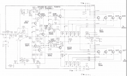
Here is the original schematic of Philips AH578
Very good conversion ..
Note - it is possible to get better sim results with slightly different values of some components, BUT they had to be tweaked a little in the actual build.
Went through a few test-and-tweak cycles.
Went through a few test-and-tweak cycles.
>Can not see what you used for M1, M2.
Exicon Lateral MOSFETS - Our Product Range
http://www.exicon.info/PDFs/ecw20n20.pdf
and
http://www.exicon.info/PDFs/ecw20p20.pdf
Exicon Lateral MOSFETS - Our Product Range
http://www.exicon.info/PDFs/ecw20n20.pdf
and
http://www.exicon.info/PDFs/ecw20p20.pdf
Attachments
Excellent, I have never seen these, must be expensive - where did you buy ?
Earl Rapp is a member here, with just a single post : https://www.diyaudio.com/forums/solid-state/117784-philips-ah578-shematic.html#post2165270
Earl Rapp is a member here, with just a single post : https://www.diyaudio.com/forums/solid-state/117784-philips-ah578-shematic.html#post2165270
You can order them directly from Exicon website.
They're not cheap, don't remember exact price ($5-$10 each ?)
but very robust (indestructible), and supposedly "designed specifically for audio" 🙂
And they don't need drivers, source resistors, or thermal tracking.
They're not cheap, don't remember exact price ($5-$10 each ?)
but very robust (indestructible), and supposedly "designed specifically for audio" 🙂
And they don't need drivers, source resistors, or thermal tracking.
>I have such transistors.In one building.
What's your schematic?
This is for an output stage based on a diamond buffer with a current shunt by Akulinichev . .I had an idea, but I haven't done it yet.
Any hints for improvement?
Here's some comments about MOSFETs based on designs of others:
LatFETs like the Excions and the old 2SJ62/2SK1058s can break into oscillation which is why designs that use these typically have caps across the G-S on the output devices or use rather large compensation cap values on the VAS transistors. Did you see any oscillation with or without the output inductor?
Some designs also have zener + diode pairs across the gate and source to limit the maximum gate voltage. Shorting the output can destroy the MOSFETs but this addition does provide some basic overload protection.
>tcd1963
1) Exicons have Zeners built in. No need for gate protection Zeners here.
There were several discussions about this here on DIY, and it was confirmed several times already.
2) The role of caps on GS is to equalize input capacitance on both devices (P and N).
Usually N device has lower capacitance than P device, so some designers ADD extra cap on N device to make them equal.
Example: Rod Elliot's P101.
If capacitances are not equal - that may cause oscillations.
Another way of dealing with this issue, is by using DIFFERENT gate stoppers, using formula RC = constant, where R is gate stopper resistor, and C is input capacitance of the FET. Adjust R on the both devices, so RC value are equal on upper and lower FETs.
Example:
Let's say the 2SJ162 has a gate stopper of 100 Ohm and a gate
capacitance of 900pF, the RC time constant is just RgatexCgate=RC time constant,
so 100x900x10^-12=90nS. If we want 'balance' we need a resistance on the gate of
the 2SK1058 that gives the same time constant.
So, Rgate x 600pF = 90nS, solve for Rgate. In this case Rgate needs to be 150 Ohm.
Exicon double die devices: P/N have different capacitance, N device has 900pF LESS input capacitance (I actually measured
it to confirm the datasheet) so in this amp, upper Rg=470 Ohm, and lower Rg = 220 Ohm.
>Did you see any oscillation with or without the output inductor?
Nope 🙂
It's rock solid stable, like Putin's forehead.
3) In case of HexFets, extra caps 10pF - 220pF from the bases of drivers might be needed - either going to the ground, or to the rail.
That's not the case with LatFets without drivers.
Last edited:
Minek123, can you run through the method of operation for this circuit and criteria for choosing the component values.
>can you run through the method of operation for this circuit and criteria for choosing the component values
See post #13 for some info: LatFet Amp Based on Philips AH578
Topology is relatively standard:
Input op-amp, Q1/Q2 - voltage shifters/buffers, Q3/Q4 - symmetrical VAS, and M1/M2 - OS.
See post #13 for some info: LatFet Amp Based on Philips AH578
Topology is relatively standard:
Input op-amp, Q1/Q2 - voltage shifters/buffers, Q3/Q4 - symmetrical VAS, and M1/M2 - OS.
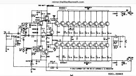
This is amp was supposedly designed/built by Philips.
Here I found on my PC, some old schematic that looks _exactly_ the same,
and it's branded as RCA 92CL-30443 amp.
RCA schematic is using different transistors.
Both amps, Philips and RCA were released in 1978.
I wonder what's the story behind this...
Did RCA work together with Philips on this? Or one copied from another..
Attachments
- Home
- Amplifiers
- Solid State
- LatFet Amp Based on Philips AH578