analog_sa said:
Not sure if we're talking about the same. It's been a long time but from what i remember creating a compound opamp is not trivial. Unless, of couse you have spice data for both chips.
I would imagine one needs to draw a Bode plot in order to confirm stability of the compound opamp for the desired gain. As no compensation caps are shown in the schematic i wonder if Russ ever worried about this. The fact that the amp actually works in a real load does not indicate a good stability margin.
the topic at hand involves stability. now this design doesn't try to make a compound opamp -- if it did, U2 would be used open loop, or at least at a high gain. the cricuit is essentially a buffer -- inverter -- high power inverter. there is no AC feedback spanning multiple amplifiers -- the extra "feedback" path is a DC path. so long as there isn't positive feedback on this path (hooked up to wrong terminal), the amp is fine.
i'd have to check the resistor values.
if it did, U2 would be used open loop, or at least at a high gain
You're absolutely right; i'll have to readjust my glasses - never noticed the 22k. Or 100uF 🙂
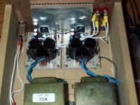
Ok, I changed the resistor values as Chris suggested (adjusted for what I had in stock) and I can say it was a good move. The amp seems to have more "energy" and headroom now. I think lowering the gain on the LM3886 helped substantially. I am really enjoying this amp. Excellent transient response. I have been listening to classical music all day so far. I will try some rock/alternative later.
All in all a very successful experiment!
The DCoffset is 3.4mv on both channels. Not bad....
I added a 10K3W resistor across the rails to drain the big caps after power down. 🙂
Cheers!
Russ
All in all a very successful experiment!
The DCoffset is 3.4mv on both channels. Not bad....
I added a 10K3W resistor across the rails to drain the big caps after power down. 🙂
Cheers!
Russ
Attachments
Just out of curiosity......
Where are you reading this:
"But.... there is more to it. The first half of the the opamp is a buffer to the second half of the the opamp, which has a positive effect (as I am reading in "Optimizing Op Amp Performance") on the inverting second half of the opamp which is the "real" buffer to the LM3886. The advantage there is the better small signal response of the inverting OPA227 with the high input impedance advantage of the non-inverting half. I am not the first to try this topology BTW."
Haven't come across that before. I wonder if it is germane to your application. As I said.........you need to consider how it is going to sound.
Jocko
Re: Just out of curiosity......
It sounds great....
It boils down to this....
U1A buffers the signal into the second half which has low impedance input and is inverting.
U1B applies a gain of 2 to the signal and buffers the LM3886 which is at a gain of 14.
In the end, it is beyond conjecture now, them amp is built, and it sounds fabulous. 🙂 More on that later... 🙂
I will leave some of the questions as to why it works to you. I am still doing my own research and "Optimizing Op Amp Performance" is only one of the books I am reading. It was a good experiment, and it turned out my best amp ever (well so far...). 🙂
Next I think I will create my own fully discrete opamp just so I more completely understand how they work.
Cheers!
Jocko Homo said:
Haven't come across that before. I wonder if it is germane to your application. As I said.........you need to consider how it is going to sound.
Jocko
It sounds great....
It boils down to this....
U1A buffers the signal into the second half which has low impedance input and is inverting.
U1B applies a gain of 2 to the signal and buffers the LM3886 which is at a gain of 14.
In the end, it is beyond conjecture now, them amp is built, and it sounds fabulous. 🙂 More on that later... 🙂
I will leave some of the questions as to why it works to you. I am still doing my own research and "Optimizing Op Amp Performance" is only one of the books I am reading. It was a good experiment, and it turned out my best amp ever (well so far...). 🙂
Next I think I will create my own fully discrete opamp just so I more completely understand how they work.
Cheers!
Sounds good?
You would drool with a (PMD100 + AD1862 + AD847 I/V + direct output) dac, AD815 pre, unbuffered NI (low value resistors) LM3886 with CRCCS PSU.
Transparency on the limits of believing. 😎
Seems like you will sooner use more parts on the amp than all this.
You would drool with a (PMD100 + AD1862 + AD847 I/V + direct output) dac, AD815 pre, unbuffered NI (low value resistors) LM3886 with CRCCS PSU.
Transparency on the limits of believing. 😎
Seems like you will sooner use more parts on the amp than all this.
Re: Sounds good?
Hmmmm, that or a beer... I am sure it sounds great Carlos, but I too busy rocking out over here to fly all that way... 😀
Really this sounds incredible... Better than I hoped.
Thanks for all the great input.
Cheers!
Russ
carlosfm said:You would drool with a (PMD100 + AD1862 + AD847 I/V + direct output) dac, AD815 pre, unbuffered NI (low value resistors) LM3886 with CRCCS PSU.
😎
Hmmmm, that or a beer...
I am sure it sounds great Carlos, but I too busy rocking out over here to fly all that way... 😀Really this sounds incredible... Better than I hoped.
Thanks for all the great input.
Cheers!
Russ
Re: Sounds good?
Carlos, I have already built amps very similar to that. This was a very nice change of pace. 🙂 What eats you about it?
carlosfm said:You would drool with a (PMD100 + AD1862 + AD847 I/V + direct output) dac, AD815 pre, unbuffered NI (low value resistors) LM3886 with CRCCS PSU.
Transparency on the limits of believing. 😎
Seems like you will sooner use more parts on the amp than all this.
Carlos, I have already built amps very similar to that. This was a very nice change of pace. 🙂 What eats you about it?
Re: Re: Sounds good?
Right, similar.
Russ White said:Carlos, I have already built amps very similar to that.
Right, similar.
Re: Re: Re: Sounds good?
And very likely better.. 😉 Well to the most important person anyway... ME. 🙂
carlosfm said:
Right, similar.
And very likely better.. 😉 Well to the most important person anyway... ME. 🙂
Russ White said:Ok, I changed the resistor values as Chris suggested (adjusted for what I had in stock) and I can say it was a good move. The amp seems to have more "energy" and headroom now. I think lowering the gain on the LM3886 helped substantially. I am really enjoying this amp. Excellent transient response. I have been listening to classical music all day so far. I will try some rock/alternative later.
All in all a very successful experiment!
The DCoffset is 3.4mv on both channels. Not bad....
I added a 10K3W resistor across the rails to drain the big caps after power down. 🙂
Cheers!
Russ
well, in this case i say good, however remember the gain of this modified circuit is a little bit higher then the one you listed. in many cases, merely listening to slightly louder music can seem to bring out more detail, impact, energy, ect...
really, with the chipamps, anything beyond the schematic shown in the datasheet* is extra. not to say these modifications aren't worth exploring, but from the engineering standpoint, well, the added complexity almost nevers serves a purpose.
*exception of the inverting config listed in the 4780 datasheets which has errors. i've emailed them twice on this one.
Yes, I had thought of that, but it truly beyond that. I have been listening at all sorts of different volumes, the volume knob never stays in one place all day. 🙂 I think that what I am hearing is a result of the LM3886 itself being at lower gain, which I know from past experience does have positive efftects, especially inverting. 😀 Still that is a very good tip.theChris said:well, in this case i say good, however remember the gain of this modified circuit is a little bit higher then the one you listed. in many cases, merely listening to slightly louder music can seem to bring out more detail, impact, energy, ect...
In this case, I think it works because the stages compilment each other. The first stage aids the inverting opamp, the secondstage aids the low gain inverting power opamp. It seems many agree that virtually any inverting opamp(power or otherwise) benefits from a fast buffer.theChris said:
really, with the chipamps, anything beyond the schematic shown in the datasheet* is extra. not to say these modifications aren't worth exploring, but from the engineering standpoint, well, the added complexity almost nevers serves a purpose.
*exception of the inverting config listed in the 4780 datasheets which has errors. i've emailed them twice on this one.
The next test I will do is toi use the AD8620 as it has a bit higher current outpout capability, and it is a bit faster yet still well compensated internally.
Russ White said:I think that what I am hearing is a result of the LM3886 itself being at lower gain, which I know from past experience does have positive efftects, especially inverting. 😀
That's my experience too, and I have posted this several times.
They work better with gains up to 20~22, which are fine for a power amp.
This is true for inverting or non-inverting.
The rest of the gain should be on the preamp, instead of using more gain on the power amp chip and a volume pot (with or without buffer) behind it.
Russ White said:It seems many agree that virtually any inverting opamp(power or otherwise) benefits from a fast buffer.
Yes, but the OPA2227 is not exactly fast...
Russ White said:The next test I will do is toi use the AD8620 as it has a bit higher current outpout capability, and it is a bit faster yet still well compensated internally.
That's much faster.😀
A very good project
I think Russ is doing a very good job in taking an old version of Mauro's amp and updating it with other chips and supplies.
Mauro's final version of his design in a way straitjackets the gainclone project. You can only use a certain chip (318) and a certain supply to be unconditionally stable. In the end it's not as DIY as I would like it to be, where you can pick your parts to "play" and make your "personal" version, as gainclone projects were being.
By building both versions and comparing them, Russ is doing us all a great help.
This is quite likely the version I will build first, using the AD8620 I also recommended to him, and my own touches in pcb layout.
Good work, Russ!
Carlos E. Martínez
- Status
- Not open for further replies.
- Home
- Amplifiers
- Chip Amps
- Latest experiment... Inverting-NOT