Russ White said:Ahh now you are more clear, at least on one point. You earlier remark made it sound like I was not using the LM3xx regs. Yes, I had seen that arrangement for PSSR rejection, I wouldn't mind adding that. 🙂
It's not a question of being more clear, I like to give a hint.
I knew you would get there.
Russ White said:Your point about the opamp inverting the signal makes no sense. If an opamp(or any amp) inverts a signal does that mean the inversion is the purpose for the component being in the circuit? Carlos, that is silly.
Thats like saying a person only build an IGC simply because they want an inverted signal or because they enjoy reversing speaker wires. 🙂
This is not a new concept, look at the thread I reference earlier. 🙂
😕
What is it Russ, are you dreaming?
You didn't understant anything I said.
Also, you don't have any idea what are you talking about.
The IGC needs an input buffer, did I say otherwise?
Aaahhh, forget it.
Move on.
PS: you now need diodes on the regs. But you know this, don't you?
carlosfm said:
It's not a question of being more clear, I like to give a hint.
I knew you would get there.
😕
What is it Russ, are you dreaming?
You didn't understant anything I said.
Also, you don't have any idea what are you talking about.
The IGC needs an input buffer, did I say otherwise?
Aaahhh, forget it.
Move on.
PS: you now need diodes on the regs. But you know this, don't you?
Now Carlos chill out friend. I value your input very much, lets not go insulting each other.
I will be the first to admit I don't know a dang thing. 🙂 So you pointing that out makes no difference to me, after all I have been doing this less than 8 months.
I believe I understood all that you said, if you think I did not, please excuse my ignorance and educate me... Please!!! 😀
Oh, yeah, and I am a persistant dreamer... 🙂
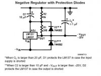
Russ White said:And here is the schematic for diode protected regulator. Notice that you only need this if the inputs can become shorted.... I really don't anticipate that... 🙂
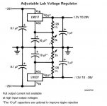
I recommend that you use the protection diodes, as you are using 'big' caps.
Read the text on the National datasheet.
Not that you will have problems without the diodes, but if you care about reliability.
Russ White said:Now Carlos chill out friend. I value your input very much, lets not go insulting each other.
There's no insult at all, anywhere.
You opened this thread to ask for advice, and then you don't take an advice.😕
My intention was to try to help, and I'm sure Jocko too.
But you have pretty much everything settled, so go on...
You opened this thread to ask for advice, and then you don't take an advice.
How do you get the impression I am not taking advice? My intention with this circuit is to evaluate the impact of the opamp on this circuit, how can I move forward with that hypothesis if I remove the key component from the experiment?
Honestly that makes no sense to me.
Russ White said:How do you get the impression I am not taking advice? My intention with this circuit is to evaluate the impact of the opamp on this circuit, how can I move forward with that hypothesis if I remove the key component from the experiment?
Honestly that makes no sense to me.
That's why I say you didn't understand anything I said.
You are using a double op-amp, inverting the second half (channel).
I just said that this second channel (the inverting op-amp on your schematic) is not necessary.
Keep the input NI buffer, and if you like them, use the OPA227 (single) instead of the OPA2227 (double).
And invert the cables on the output of the amp, to keep the phase.
I understand what you are doing with this circuit and your intention, but really, cascading op-amps starts impacting on transparency.
I suppose you are doing an integrated amp, you don't need that.
As I said, you have everything settled, and you wanna make an experiment, so go on...
Your suggestion makes perfect sense, and I will do you the respect of building that configuration as well. 🙂
But.... there is more to it. The first half of the the opamp is a buffer to the second half of the the opamp, which has a positive effect (as I am reading in "Optimizing Op Amp Performance") on the inverting second half of the opamp which is the "real" buffer to the LM3886. The advantage there is the better small signal response of the inverting OPA227 with the high input impedance advantage of the non-inverting half. I am not the first to try this topology BTW.
I think that is the fundamental misunderstanding. The idea is to get the best out of both devices.
You see Carlos, I have been listening to you(and you too Jocko), but your advice has not been about this circuit, but about what your idea of a better inverting chip amp would be. Thats all well and good, I can build an amp based on those ideas as well. 🙂 But this experiment is to test the things I am learning every day. It is a hard and fast experiment which will be tested and critiqued, so I can share my findings with all of my friends.  Cheers! Time for another beer. 🙂
Cheers! Time for another beer. 🙂Russ
I have to admit to be still mystified by Mauro's amps. They seem based on the assumption that the 3886 can be substantially improved by improving its input stage. Maybe in some situations this is true.
Your circuit, otoh, does not improve any aspects of Mauro's amp. It adds, quite unnecessarily, an input buffer while at the same time omits important details from Mauro's circuit. It certainly lets you exercise your PCB creation skills but i still wonder if each and every iteration is worth publishing.
Btw, i am not convinced that it's stable as published.
sa -- it likely is. the feedback RC time constant, at least on the first iteration, was subsonic. at first i saw the second feedback path and assumed that it was used to boost open-loop gain.
if anything, the design may have aspects useful for parallel amplifier creation if the DC offset can be shown to be less. but i'm not sure if this circuit has an appreciable effect on that.
possibly it would make more sense to split the gain across the opamps? a gain of 12 for the 3886 and a gain of 2 for the vestegial inverter.
analog_sa said:Russ
I have to admit to be still mystified by Mauro's amps. They seem based on the assumption that the 3886 can be substantially improved by improving its input stage. Maybe in some situations this is true.
Your circuit, otoh, does not improve any aspects of Mauro's amp. It adds, quite unnecessarily, an input buffer while at the same time omits important details from Mauro's circuit. It certainly lets you exercise your PCB creation skills but i still wonder if each and every iteration is worth publishing.
Btw, i am not convinced that it's stable as published.
SA which Mauro design are you referring to? And I certainly did not expect to think it would be an automatic improvement. Especially not over his "REF" design. This one is not as all like that one. It is very much like his NIGCWIPS. This experiment is born of tests I performed on the OPA227 itself in inverting mode being driven by a buffer, its not really all about the LM3886.
BTW it is quite stable. Listening right now. 🙂
I will measure this afternoon. So far to my ears it sounds almost identical to Mauro NIGCWIPS(Non-inverting GC with inverting power stage), but it seems to have lower noise(at least my sound card SA says so). I will test it with a real sprectrum analyzer today.
You can read about Mauro NIGCWIPS here:
http://www.diyaudio.com/forums/showthread.php?postid=622225#post622225
Also note the ease in which the circuit can be modified with a pot between the opamp halves for a simple integrated volume control. In many respects my circuit is like Mauro's only monobloc and with Lm3x7 regulators and not shunt regulators.
Cheers!
Thanks to those of you who where actually helpful. Especially you Carlos. 😉
theChris said:sa -- it likely is. the feedback RC time constant, at least on the first iteration, was subsonic. at first i saw the second feedback path and assumed that it was used to boost open-loop gain.
if anything, the design may have aspects useful for parallel amplifier creation if the DC offset can be shown to be less. but i'm not sure if this circuit has an appreciable effect on that.
possibly it would make more sense to split the gain across the opamps? a gain of 12 for the 3886 and a gain of 2 for the vestegial inverter.
That is an an interesting idea splitting the gain, any suggestions for changes in the resistor values to accomplish this?
off top of head:
R1, R9 -- 47.0k, 3.30k (Av ~ -14)
R8, R7 -- 47.0k, 22.0k (Av ~ - 2)
R2 -- 15k
R6 -- 15k
R5 -- 0.330k
R4 -- 15k
R10 -- 3.08k
choices were made to minimize DC offset and reduce loading on opamps.
U1: +(15.33k) -(15.00k) L(22.00k)
U2: +(15.00k) -(14.98k) L(3.08k)
U3: +(3.08k) -(3.08k) L(0.008k)
however, after glancing at the opa2227 datasheet, i am not sure on some of these values. specifically, the datasheet seems to want some of the values to be higher and others lower.
lower impedances on the inputs would lower noise. further, the datasheet mentions internal circuitry that would remove or reduce some resistors. not sure on the how the opamp reacts to low impedance loads.
Wow thanks Chris!! Good info.
The opa227 seems to me to be fine with low impedance loads, as I have used it for headphone amps with good success.
The opa227 seems to me to be fine with low impedance loads, as I have used it for headphone amps with good success.
sa -- it likely is. the feedback RC time constant, at least on the first iteration, was subsonic. at first i saw the second feedback path and assumed that it was used to boost open-loop gain.
Not sure if we're talking about the same. It's been a long time but from what i remember creating a compound opamp is not trivial. Unless, of couse you have spice data for both chips.
I would imagine one needs to draw a Bode plot in order to confirm stability of the compound opamp for the desired gain. As no compensation caps are shown in the schematic i wonder if Russ ever worried about this. The fact that the amp actually works in a real load does not indicate a good stability margin.
As no compensation caps are shown in the schematic i wonder if Russ ever worried about this. The fact that the amp actually works in a real load does not indicate a good stability margin.
Hi SA. I honestly do not know enough to worry about much. 😉 Do you have sugesstions for compensation caps? That is why I am doing this... to learn. So if you can point me in the right direction that would be great. 🙂 The opamps I am using are unity gain stable (save the LM3886) , so should I need compensation caps? If I do would they simply go between the opamp out and inverting input? What values would you start at? 10-100pf?
Chris,
I was going to change to your values, I substituted values I actually have in stock. I kept the 100K for R4 so my corner frequency is the same for the high pass filter.
R1 47K
R2 12K
R3 1R
R4 100K
R5 470R
R6 12K
R7 22K
R8 47K
R9 3.2K
R10 3.2K
R11 10K
R12 20K
R13 200R
R14 2.2K
R15 200R
R16 2.2K
Does this look sane?
Russ
I don't know. I don't even know what your opamps are. Apparently Mauro has given this some consideration in his design. Can it be a real problem? I guess if the amp works in a large electrostatic speaker without any fancy impedance compensation networks then all is well 🙂
I don't know. I don't even know what your opamps are. Apparently Mauro has given this some consideration in his design. Can it be a real problem? I guess if the amp works in a large electrostatic speaker without any fancy impedance compensation networks then all is well 🙂
- Status
- Not open for further replies.
- Home
- Amplifiers
- Chip Amps
- Latest experiment... Inverting-NOT