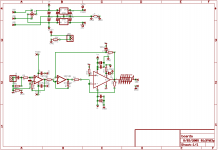
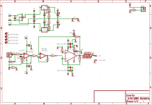
Ok, this one is a little hard to follow at first. Borrowing from some ideas I have gotten from Mauro and others I have created a design that uses a LM3886 and a OPA2227 (dual low noise opamp) to create a non inverting amp, but the LM3886 is operated as inverting. Basically a double inversion with a buffer input.
The first part of the OPA2227 is simply a high input impedance buffer, which feeds the signal through the second gate in inverting mode, that signal is input to the LM3886 in inverting mode, so the final output is not inverted(or completely flipped, which ever you prefer🙂).
Here is the schematic.
Sorry, its a mess.
Attachments
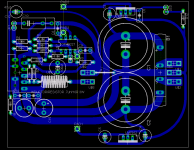
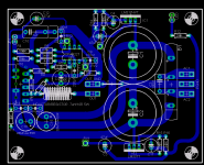
It is all still very preliminary. I am just looking for some ideas on values and such. 🙂 You will noticethe PCB is not finished (no mounting holes even).
GeWa said:You really honour your signature, aren't you😀
Regards
Hey, its better than psychotherapy. 🙂


Why put a op-amp in the middle just to serve as an inverter??? They almost never sound good. I would rather leave it inverting, and flip the speaker leads.
OK.........you do need some sort of buffer to run it in the inverting mode, but I would not use an op-amp with unity gain.
Jocko
OK.........you do need some sort of buffer to run it in the inverting mode, but I would not use an op-amp with unity gain.
Jocko
Jocko Homo said:Why put a op-amp in the middle just to serve as an inverter??? They almost never sound good. I would rather leave it inverting, and flip the speaker leads.
OK.........you do need some sort of buffer to run it in the inverting mode, but I would not use an op-amp with unity gain.
Jocko
You make some pretty aweful assumptions...
A good opamp makes an excellent buffer, and the purpose of the opamp is not "only" to invert the signal.
The worst assumption is about the sound. I have built an amp like this (but it was Maruo's design which is slightly different) and it sounds superb.
One of the reasons this works well is the very low output impedance of the opamp, as well as slew rate and other virtues.
Cheers!
Russ
question1.
what are R2, C7 for? i can only assume it is DC-offset related.
q2:
why do all inputs have resistors?
q3:
what reason did you have for the choice of resistors?
q4:
why not run the feedback path to the first opamp?
what are R2, C7 for? i can only assume it is DC-offset related.
q2:
why do all inputs have resistors?
q3:
what reason did you have for the choice of resistors?
q4:
why not run the feedback path to the first opamp?
theChris said:question1.
what are R2, C7 for? i can only assume it is DC-offset related.
q2:
why do all inputs have resistors?
q3:
what reason did you have for the choice of resistors?
q4:
why not run the feedback path to the first opamp?
q1
Yes R2,C7 act to nullify DC.
q2 Well, partly to help set gain for some stages, but on the first stage it is to form a low pass filter to filter out RF.
q3 I was just using values I had used in the past for other applications. Some values I used just because they got me the gain I was looking for.
q4 The reason is the the first opamp gate is purely a buffer to aid the inverting opamp stage.
I am using techniques similar to the ones found here:
http://www.diyaudio.com/forums/showthread.php?postid=622225#post622225
Looking over that thread may answer a lot of your questions.
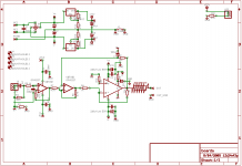
Almost ready to etch...
I have changed the regulators do to some great input from carlmart and others.
I also added the rest of the missing pieces. I think its ready to go. 🙂
The resistor at output can either be 10R 5W with a .7uH inductor wound around it, or .3R 7W.
Here is the current schematic (still a mess sorry).
I have changed the regulators do to some great input from carlmart and others.
I also added the rest of the missing pieces. I think its ready to go. 🙂
The resistor at output can either be 10R 5W with a .7uH inductor wound around it, or .3R 7W.
Here is the current schematic (still a mess sorry).
Attachments
Jocko Homo said:Why put a op-amp in the middle just to serve as an inverter??? They almost never sound good. I would rather leave it inverting, and flip the speaker leads.
I agree with this, but what the hell...😀
Russ White said:Here is the current schematic (still a mess sorry).
Russ, if you can have lower noise and lower output impedance with the LM3x7 regs, why don't you?
Ummm.. I am..carlosfm said:
Russ, if you can have lower noise and lower output impedance with the LM3x7 regs, why don't you?
Also, the purpose of the opamp is not to flip the signal at all.
Russ White said:Ummm.. I am..
No, you're not.
The way you are using the LM3x7 regs they don't have much advantage over the 78xx/79xx.
For instance, you need caps across the Adj. resistors to ground.
I suggest 47uf.
Russ White said:Also, the purpose of the opamp is not to flip the signal at all.
It's the same thing, the op-amp is inverting the signal.
carlosfm said:
No, you're not.
The way you are using the LM3x7 regs they don't have much advantage over the 78xx/79xx.
For instance, you need caps across the Adj. resistors to ground.
I suggest 47uf.
It's the same thing, the op-amp is inverting the signal.
Ahh now you are more clear, at least on one point. You earlier remark made it sound like I was not using the LM3xx regs. Yes, I had seen that arrangement for PSSR rejection, I wouldn't mind adding that. 🙂
Your point about the opamp inverting the signal makes no sense. If an opamp(or any amp) inverts a signal does that mean the inversion is the purpose for the component being in the circuit? Carlos, that is silly.
Thats like saying a person only build an IGC simply because they want an inverted signal or because they enjoy reversing speaker wires. 🙂
This is not a new concept, look at the thread I reference earlier. 🙂
Thanks for reminding me of the data sheet tip for PSSR on the regs though, not a bad idea.
There are other ways to make a low-z source. And no, I am not making a lot of assumptions. I just know different. But you are free to proceed as you please. I gave you some hints.
Jocko
Jocko
Jocko Homo said:There are other ways to make a low-z source. And no, I am not making a lot of assumptions. I just know different. But you are free to proceed as you please. I gave you some hints.
Jocko
And I assure you I respect your opinion, and I said this is an experiment, and yes it is my own. 😉 I am sure there are many ways to get a low Z source, and this is just one.

- Status
- Not open for further replies.
- Home
- Amplifiers
- Chip Amps
- Latest experiment... Inverting-NOT