OPA 454 can act as a good driver also. I am waiting for samples to pair with an INA to boost the voltage to hopefully 200-300.I bought mine, alf16n(p)16w, from Newark, when they had them on special a few years back now.
On the subject of Latfet designs, I have done a layout of the Mark Alexander CFA amp. I bought the parts many years ago, I guess waiting for another retirement project. I did not get the Toshiba igbt devices as they were impossible for me to buy. So I think the latfets should work out okay.
Anyone interested in doing a design/layout review? I have managed to lay it out on a 100x100mm 2 layer pcb, so i can get the $13USD special deal from pcbway for 10 pieces.
Let me know if anyone is interested i will start a new thread and we can go from there. I am not interested in making any $, just the fun of designing the ckt and checking it out. I have some ssm2131 opamps and I believe my source has more if I need them, but other opamps should work as well, ie OPA604 or OPA62(3)7.
Driver stage is omitted lfets are being pushed right out of the class A, VAS stage.
I have seen a lot and tried a lot too. I think the result will not be very good. You need proper drive for latfet.
I do not believe i will be using many PCBs, I don't trust my abilities for proper grounding with home etching so will be doing everything point to point.
I think PCB is easier for HF. With PTP you can control the DC but not the HF.
i have a bunch of bridges but flipped it to Shottsky diodes for FWB rectification so i have a bunch i don't have a use for at this point. figure fastons allow me to take it apart faster and easier should the need arise.
May be we should break some bridges to see what is inside. I found I prefer discrete diodes than most bridges.
In any Language ... including English 😀So with alloy you always meant aluminum....OK, now I get it. In my language, alloy is just about any mixture of any metal.
alloy
[noun al-oi, uh-loi; verb uh-loi]
noun
1.
a substance composed of two or more metals, or of a metal or metals with a nonmetal, intimately mixed, as by fusion or electrodeposition.
Funny thing is`that Steel cases ... are also "alloy" , by definition.😀
http://www.bcae1.com/repairbasicsforbcae1/images/transistordies/IMG_5503_Hitachi_2SJ50b.jpg
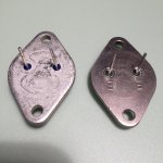
- The pitting of the mounting plate surface demonstrates it's an alloy with aluminum as the highest volume portion.
- As does the chewing-gum appearance of the remains of the sawn-off hat.(thicker than a steel TO3 hat)
Area of an ellipse : (Pi x height x width)/4
TO3 mounting plate for pure aluminum : (3.14 x 4 x 2.5 x 0.33*)/4 x 2.7 ~ 7 grams
* mounting plate thickness is 3.3mm max.
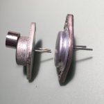
See the texture and color of the heat spreader under the die, mind the top part, much softer material (<= indent) than aluminum.
The much higher specific weight of the heat spreader accounts for the lost grams of the 18 total.
A Dutch electronics magazine carried a detailed analysis of the Hitachi TO3 case composition in the late 1980s.
Hitachi never did in any of the lateral MOSFET application notes, not even in the 74-page publication of 1985.
=> notice the punching rupture line on the side of the mounting plate. The location is a giveaway of the aluminum volume percentage of the alloy.
Thank you for the explanation. I have noticed that a small magnet will stick to the mounting plate and the top part but not to the heat spreader. So what did Hitachi mix with the aluminum then? Can you post the analysis from the Dutch electronics magazine?
Last edited:
Did you measure Black Gate also? I usually don't add smaller bypass cap when using Black Gate. Currently I'm working with Apex' FX8 where the front end supply is the main supply RC filtered with 10 Ohm and 47uF. I'm using BG. Do you think I should parallel with MKP/FKP? What size?
Why i don´t have it.The Black Gate production has stopped in 2006 https://en.wikipedia.org/wiki/Black_Gate_(capacitor)
I have seen a lot and tried a lot too. I think the result will not be very good. You need proper drive for latfet.
I think PCB is easier for HF. With PTP you can control the DC but not the HF.
May be we should break some bridges to see what is inside. I found I prefer discrete diodes than most bridges.
I was going to push the lfets with an mje350 after some bc549/559 and mpa42s. Do you think anything should come after the mje? 47 uf caps are boot strapped to the lfet in addition to the typical resistors. Power rails will have some additional capacitance also. I am using diodes for rectification. I was going to use the excess bridges on the ground to give me 4 fast on connections. I am not confident in my ability to properly build a ground plane on a home brew pcb. I may use ginger board or something else but etching grounds - and having the best conduction well, I'm not sure about.
I have noticed that a small magnet will stick to the mounting plate and the top part but not to the heat spreader.
Thermal conductivity of aluminum is multiple times the one of steel, it doesn't require additions for thermal reasons (in particular as the thickness of the mounting plate is over 3mm).
Close to 100 percent and pure aluminum is very soft, only used for stuff as alu wrapping foil and the honeycomb of car radiators.
Every other aluminum product is an alloy, with traces of copper and iron, the latter makes it slightly magnetic.
The hat of a TO-3 case is cold press molded, 3000 series aluminum alloy, 0.7 percent iron.
Last edited:
I was going to push the lfets with an mje350 after some bc549/559 and mpa42s. Do you think anything should come after the mje? 47 uf caps are boot strapped to the lfet in addition to the typical resistors.
The choice looks good. Bootstrapping for higher voltage gain. I think MPSA42 is the voltage stage. Perfect high hfe with low Cob, especially if hand selected (only issue is Vce of course). MJE350 is not the driver (I'm not sure about definition here)? So cascaded with MPSA?
I am not confident in my ability to properly build a ground plane on a home brew pcb. I may use ginger board or something else but etching grounds - and having the best conduction well, I'm not sure about.
You can tin the track or use solid wire if thickness is the problem. I always do that. I think the problem is not etching, but layouting, but it is not so different with PTP imo. For prototyping I use veroboard, for etching I also draw by hand based on the "dots" of veroboard (smallest one to ensure minimum loop, using smallest resistors when possible).
Thermal conductivity of aluminum is multiple times the one of steel, it doesn't require additions for thermal reasons (in particular as the thickness of the mounting plate is over 3mm).
Close to 100 percent and pure aluminum is very soft, only used for stuff as alu wrapping foil and the honeycomb of car radiators.
Every other aluminum product is an alloy, with traces of copper and iron, the latter makes it slightly magnetic.
The hat of a TO-3 case is cold press molded, 3000 series aluminum alloy, 0.7 percent iron.
No, look at the attached pictures. The magnet sticks with a "smack" noice.
The Motorola transistor is made of an aluminum alloy and does not stick to the magnet at all. All standard aluminum alloys contains <0.7 % iron but they are all non-magnetic.
Attachments


The choice looks good. Bootstrapping for higher voltage gain. I think MPSA42 is the voltage stage. Perfect high hfe with low Cob, especially if hand selected (only issue is Vce of course). MJE350 is not the driver (I'm not sure about definition here)? So cascaded with MPSA?
You can tin the track or use solid wire if thickness is the problem. I always do that. I think the problem is not etching, but layouting, but it is not so different with PTP imo. For prototyping I use veroboard, for etching I also draw by hand based on the "dots" of veroboard (smallest one to ensure minimum loop, using smallest resistors when possible).
I guess I will have to show you. I am not up to speed with all the terms so if you look at my last posts you see a lot of people jumping down my throat. Mje350 is tech the driver but not a true driver state. Bootstraping the in with an additional 47uf cap. For what I paid of like 5 each component and couldn't get the mje for 30 more I could have ordered 100 so if you think these pairing are good I'll order 100 of each. I think they are prob the best tranny for the job. I'll return the other ones as much as it pisses him off but I'll get some other **** to make it up. What's the best way to pair transistors?
Or bench? I would like to bread board a particular area then check, focus on one stage at a time with little change. Optimize each zone in a live setting on breadboard. Ptp seems to be the best way to do things ans for items like HF I can ginger or vero board them and use stand offs.
I have the rub off etchings and programs and I'm pretty sure I can run traces thick and clean but is the a place you can point me to to optimize the ground plain?
The choice looks good. Bootstrapping for higher voltage gain. I think MPSA42 is the voltage stage. Perfect high hfe with low Cob, especially if hand selected (only issue is Vce of course). MJE350 is not the driver (I'm not sure about definition here)? So cascaded with MSA.
Mje is tech the driver but isn't being used in complementry pairs or anything for a true driver output as were bipolors would need a full driver stage - i am driving right out of class A stage (VAS) stage with just one mje350. I am getting some 340s also just incase I want to add a complementry pair/cascade/cascode/mirror and then still drive with the 350 for more stability.
smack
Hold your magnet to the leads of the Hitachi device, steel.
Magnesium has half the magnetic susceptibility of aluminum, but a magnesium gearbox acts soft magnetic, despite a Km barely over 1.
Only hard magnetic metals are iron, nickel and cobalt. (not counting manganese or buckyballs)
Stuff like alnico is highly ferromagnetic, but can only be casted, at least two times as heavy as aluminum, and hardly corrodes.
As you confirmed, regular aluminum alloys contain 0.7 percent iron or less.
4000 series are 0.8 percent, but most of the high silicon types are intended as welding wire.
8000 series go up to 1 percent Fe, but very very unlikely to have been used for a transistor case.
Of 1000-7000 series alloys, the TO-3 hat can only have been press (pulled) formed with either 3xxx or 5xxx aluminum alloy.
(btw, tungsten rods are what I used to arc weld aluminum with, it's silly heavy. aluminum-tungsten alloys are new to me)
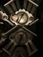
post69 Pic2 left side shows the "8" shaped copper slug in the surrounding steel backplate.No, look at the attached pictures. The magnet sticks with a "smack" noice.
The Motorola transistor is made of an aluminum alloy and does not stick to the magnet at all. All standard aluminum alloys contains <0.7 % iron but they are all non-magnetic.
The right device shows a thin curved line.
Is that the edge of a copper slug in the middle of the aluminium alloy backplate?
tungsten is also rather expensive, so I cannot see it being used without very good reasons(btw, tungsten rods are what I used to arc weld aluminum with, it's silly heavy. aluminum-tungsten alloys are new to me)
Sorry but that *thick* steel base transistor is a fake in my book.
Thick copper is good; thick iron is useless.
The "8" shaped copper plug is an attempt to correct this; good on choice of material, bad because it wastes base surface (the iron part does not count for all practical purposes).
Thick copper is good; thick iron is useless.
The "8" shaped copper plug is an attempt to correct this; good on choice of material, bad because it wastes base surface (the iron part does not count for all practical purposes).
My very old To3 Toshiba 2n3773 have the "8" copper slug in the steel surround.
My ONsemi To3 MJ15003/4 & MJ21193/4 show a plain steel backplate.
My ONsemi To3 MJ15003/4 & MJ21193/4 show a plain steel backplate.
My very old To3 Toshiba 2n3773 have the "8" copper slug in the steel surround.
Looks like my collection of GE/RCA 2N3772. Unfortunately they are highly magnetic (if it matters), but strangely they are very clean and shiny, free from any corrosion.
I have another casing from Motorola, very robust, the heaviest type that I know, more like stainless but slightly dark, but strangely non-magnetic.
BTW, Andrew, do you have any kontra opinion regarding my carbon composition application for VHF zobel? I can change those to MOX resistors instead.
Sorry but that *thick* steel base transistor is a fake in my book.
Thick copper is good; thick iron is useless.
The "8" shaped copper plug is an attempt to correct this; good on choice of material, bad because it wastes base surface (the iron part does not count for all practical purposes).
No, it is not a fake. Here is a picture from a working amplifier that has never been repaired. The magnet sticks to the top in the same way.
Attachments
If you have your output Zobel/s located on the output devices with ultra short traces to Power Ground, then there may be an advantage to using low inductance carbon composition for the R of the Zobel..............BTW, Andrew, do you have any kontra opinion regarding my carbon composition application for VHF zobel? I can change those to MOX resistors instead.
Any longer wires/traces would completely negate the low inductance.
If the resistors plus capacitors have a route length from output device to Power Ground that is longer than an inch or so, then forget about any advantage that composition may offer.
Any longer wires/traces would completely negate the low inductance.
If the resistors plus capacitors have a route length from output device to Power Ground that is longer than an inch or so, then forget about any advantage that composition may offer.
Thanks. It is hard to keep the trace less than an inch... Even tho I have connected the zobel directly between output and midpoint of local decoupling, under the board... Or may be it is better to take the input directly from Source pin of N-channel mosfet?
Last edited:
- Home
- Amplifiers
- Solid State
- Lateral MOSFETs