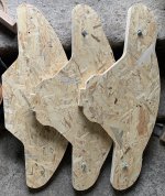
Some time ago, I had a 1" horn designed by Joseph Crowe - as large as possible if printed in 4 pieces on my 3D printer. I never got beyond some test prints and the printer is in a never-ending upgrade process. Since I have bought some 1.4" exit drivers meanwhile, I scaled the model 1.4x and modified a bit for layered CNC construction. For the test, I went on the cheap side using 15 mm OSB flooring panels. The dimensions are 725 x 300 x 380 mm (WxHxD). I have 20 layers cut, glued in pairs ready for 3D machining. I just tried to lay the parts on the CNC in the correct order and it looks pretty impressive. Heavy as hell, too. This piece serves like a learning object to get some machining skills for fabrication of such large horns.
Attachments


WOW - what a cool - novel way to obtain a smooth expansion ! Are you still using a little Paraflex 12 for midbass duty?
Yes, but still only one. The other is just a simple bass reflex with the same speaker. I really need to make some detailed comparison. Now I have a bunch of single speaker prototypes and not many working stereo pairs.
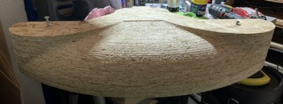
It begins to look like a horn already🙂 The roughing step was 3 mm. During the week, I will try to finish all the parts with a ball mill. It would look much better in plywood or hardwood.

You are always doing some cool s*it. Thanks for sharing your experiments!It begins to look like a horn already🙂
+1You are always doing some cool s*it. Thanks for sharing your experiments!
penalj, you have more (really neat) projects in the works, than anybody i've seen post
Yes, cool stuff! And who knows, maybe the grainy particle nature of the OSB will sound great, kill resonances. 🙂
You could always surface coat your horns with fiberglass resin and then machine them again with your CNC router running a sharp ball nose bit.
Last edited:
If doing it that way, the underlying frame (OSB or ply or whatever) would not need to be solid - you could use thin, spaced pieces like this:You could always surface coat your horns with fiberglass resin and then machine them again with your CNC router running a sharp ball nose bit.
...stretch a "skin" over them (something like stocking material) and then apply resin to the fabric.
I was suggesting using fiberglass resin (NO fiberglass mat). The purpose of the resin is to fill and close off the wood pores and tie down 'the fuzzies' in the OSB. That should give a machinable surface that could hold a finish.
A similar thing could be realized using automobile bondo. Spread on a thin layer of quality automobile bondo instead of a fiberglass resin. Bondo machines surprisely well.
A similar thing could be realized using automobile bondo. Spread on a thin layer of quality automobile bondo instead of a fiberglass resin. Bondo machines surprisely well.
Last edited:
Ah, my mistake, I misread you.I was suggesting using fiberglass resin (NO fiberglass mat).
I thought you were suggesting fibreglass as a skin layer / to fill in the steps, so I was visualising an end result like these (or like the Azura / Oris / various other horns):
http://horns-diy.pl/
Yea, I expected that you were. I was proposing what could be done to make the horn more finished looking and prepare it for testing.
Looks nice 🙂 How much Z height do you have and what did you do to align all the pieces to cut them in multiple operations?7 parts out of ten are machined. I just could not resist🙂 Tomorrow, last 3 and then glue all 5 layers on each half.
OSB being relatively soft and coarse is probably a good thing in a stacked & laminated build. This ply build had some issues where the ply warped and the layers split apart.
https://www.diyaudio.com/community/...ers-a-25-driver-full-range-line-array.242171/

OSB can also also be mde from pretty much any woody scrap, so it is probably greener / uses fewer resources to make than an equivalent volume of ply.
https://www.diyaudio.com/community/...ers-a-25-driver-full-range-line-array.242171/
OSB can also also be mde from pretty much any woody scrap, so it is probably greener / uses fewer resources to make than an equivalent volume of ply.
My CNC has around 120 mm Z travel available. I am getting slowly to thicker stock, with my wasteboard and tools I have I can do 60 mm easily, more would need some thinking. To align the parts, I did the following:

I have a fixed board with 86 x 86 mm grid of holes. There are M6 nuts from below of the board. I made this board myself, machined hex slots for the M6 nuts from the other side , secured with a bit of ca glue. Then turned around, fixed to the original board with wood screws and flattened with a wide bit. The holes are used for 3D printed fixtures.
First, I cut the outline and two 6mm alignment holes. Machining starts from the edge of the stock (origin is bottom left corner).

The 6 mm holes are used both for alignment while gluing together and for mounting to the wasteboard. Wooden dowels will be used for the final gluing of all layers together. The extra layer of OSB is there to protect the wastboard (the ball mill goes into it) and also because the screws are too long as a spacer. The machining origin is set to the center of the right hand (bottom) screw, safe height is set to move safely above it.
A more precise way would be to use steel pins and machined holes, but this trial proved that it is not necessary for this type of object. The wood itself has larger tolerances in thickness than the error in positioning.
If I ever make the second one, I already have an idea how to machine all the slices fully in place with the 6 mm end mill only, it would only require a bit more CAM work.
I have a fixed board with 86 x 86 mm grid of holes. There are M6 nuts from below of the board. I made this board myself, machined hex slots for the M6 nuts from the other side , secured with a bit of ca glue. Then turned around, fixed to the original board with wood screws and flattened with a wide bit. The holes are used for 3D printed fixtures.
First, I cut the outline and two 6mm alignment holes. Machining starts from the edge of the stock (origin is bottom left corner).
The 6 mm holes are used both for alignment while gluing together and for mounting to the wasteboard. Wooden dowels will be used for the final gluing of all layers together. The extra layer of OSB is there to protect the wastboard (the ball mill goes into it) and also because the screws are too long as a spacer. The machining origin is set to the center of the right hand (bottom) screw, safe height is set to move safely above it.
A more precise way would be to use steel pins and machined holes, but this trial proved that it is not necessary for this type of object. The wood itself has larger tolerances in thickness than the error in positioning.
If I ever make the second one, I already have an idea how to machine all the slices fully in place with the 6 mm end mill only, it would only require a bit more CAM work.
- Home
- Loudspeakers
- Multi-Way
- Large ES-horn prototype