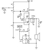
I hope this "handmade" picture helps...🙂
I hope there are no faults, I am in a hurry to go to a party in Heidelberg.....46 years Abitur celebration......two days....
see you later on monday...😀
I'm just tuning back into this - do you tie back to "-Reference" or Ground in your diagram. Ground seems possible based on prior diagrams, but only you know what you've built.
But you all can help me !!!!
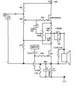
I do not know what is the better possibility grounding at 0V or at the negative reference...
I do not know what is the better possibility grounding at 0V or at the negative reference...
Attachments
Last edited:
O.k. I am never perfect, must be a disease....
I forgot in both pictures the 10k resistor going from the node point input cap and 47R gate stopper to the wiper of the 10k biasing pot of the SIT.
You can see this 10k resistor in all pictures of Mike!
And the connection from the 4k7 resistor to,the output node is not necessary.
I forgot in both pictures the 10k resistor going from the node point input cap and 47R gate stopper to the wiper of the 10k biasing pot of the SIT.
You can see this 10k resistor in all pictures of Mike!
And the connection from the 4k7 resistor to,the output node is not necessary.
Last edited:
@juanitox 😀 did you do your vote ......😀
I tried your suggestion with the self biasing and Hammond circuit.
I found it difficult in my system to hear a distinctive difference to the biasing with a separate PSU.
But the sound differences between the Hammond and thick film and CCS solutions are easy to hear even in my system.
But thank you for the suggestion to have more porn....😀
😀
the 3R5 biasing resistor delivers the biasing voltage that you can fine-tune with the 10k pot, I would keep the value of the 3R5 resistor as low as you can. It depends on the current you want to have for the 2SK82. With 2A and 3R5 you get a maximum bias voltage of 7V. That might be unnecessary high, so you can go with the resistor value a bit lower. With 1,5A you can calculate yourself....😀
the 3R5 biasing resistor delivers the biasing voltage that you can fine-tune with the 10k pot, I would keep the value of the 3R5 resistor as low as you can. It depends on the current you want to have for the 2SK82. With 2A and 3R5 you get a maximum bias voltage of 7V. That might be unnecessary high, so you can go with the resistor value a bit lower. With 1,5A you can calculate yourself....😀
Attachments
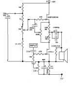
I still cannot understand the biasing network of this circuit. What is the voltage at -ref and where do you get it from?
From my point I see the vfet biased by a 3r5 to ground BUT then I see a -ref attached to the source. Since the current will flow in the path of least resistance it should flow from source to -ref and basically the source is at -ref voltage whatever resistor you may put between source and 0V.
From my point I see the vfet biased by a 3r5 to ground BUT then I see a -ref attached to the source. Since the current will flow in the path of least resistance it should flow from source to -ref and basically the source is at -ref voltage whatever resistor you may put between source and 0V.
@juanitox 😀 did you do your vote ......😀
no Merkel has done it for us 😀
i like your " brainstorming" for the CCS version, but at last what have done N.P to prefer a Res load to CCS for his bigger Sit AMP ?
no Merkel has done it for us 😀
i like your " brainstorming" for the CCS version, but at last what have done N.P to prefer a Res load to CCS for his bigger Sit AMP ?
Oh, we have Cohn here, should we send Angela to you..... but will Carla say...?😀
the brainstorming is simply because SIT-2 was published earlier and I supposed it to be a Mu-follower like J2, so I was fascinated by the idea to drive a Mu with two Semisouth alone without J-Fets. Indeed I succeeded to get it running, but the gain of the two "pentodes" was too high about 25db. Much hum and hissing was the consequence. But the sound was good and then Mike started with the SIT and it has a lower gain so I saw the chance to build a better Mu with less gain......
That is the reason I was fixed a bit on the Mu....
But for sure the resistor solution has the best details and attack at least with the thick film resistors.
I am sure Nelson saw small advantages for the resistor solution and maybe the cap he chooses is a bit more warmish and can compensate a bit the directness of the thick films.🙂
something i don"t understand in the Sit 1 pic , i can see the Two white cap for inpout and output coupling, the power supply in the center but what is for the seven big caps near the loading res , additional filtering?
I've been staring at those big caps in that picture too. Additional PS filtering, output coupling, slow start, and source R bypass are the options that come to mind.
I want to know how the gate bias voltage is generated and how the slow start is implemented in the SIT1. Knowing this would help sort those caps out.
The gate biasing circuit of the SIT2 prototype isn't obvious in the SIT1. Perhaps they are doing it differently.
The SIT1 has a nice slow turn on (~10 seconds until the bias settles). Nelson accomplished this same thing on the F2 with BIG caps, so I wouldn't be surprised to see brute force used here too.
I've never mounted a TO-3 before. Are these two pieces good candidates or are there better choices?
Insulator
Digi-Key - BER166-ND (Manufacturer - HF115AC-0.0055-AC-05)
Socket
Digi-Key - 4601K-ND (Manufacturer - 4601)
Regards,
Dan 🙂
Insulator
Digi-Key - BER166-ND (Manufacturer - HF115AC-0.0055-AC-05)
Socket
Digi-Key - 4601K-ND (Manufacturer - 4601)
Regards,
Dan 🙂
You're probably better off with mica & grease, but the socket looks fine (or, you could do without a socket)...
Roscoe
Roscoe
I picked this up because it was a complete kit.
http://search.digikey.com/scripts/D...go&lang=en&site=us&keywords=4725K-ND&x=15&y=5
4725K-ND
http://search.digikey.com/scripts/D...go&lang=en&site=us&keywords=4725K-ND&x=15&y=5
4725K-ND
Heatsinks Revisited. I'm wondering if the Wakefield 433K would work.
433K - WAKEFIELD SOLUTIONS - Heat Sink | Newark/element14 Canada
It seems to have similar thermal efficiency to the aforementioned Aavid D180-20.
D180-20 - AAVID THERMALLOY - HEAT SINK, T SLOTS | Newark/element14 Canada
Regards,
Dan 🙂
433K - WAKEFIELD SOLUTIONS - Heat Sink | Newark/element14 Canada
It seems to have similar thermal efficiency to the aforementioned Aavid D180-20.
D180-20 - AAVID THERMALLOY - HEAT SINK, T SLOTS | Newark/element14 Canada
Regards,
Dan 🙂
If that spec sheet rating means 42C above ambient, then no.
The forced air rating for the 433K is .28C/W, so .84C/W for natural convection sounds feasible, so again, no.
The D180-20 has a natural convection rating of .33C/W according to the catalog.
The forced air rating for the 433K is .28C/W, so .84C/W for natural convection sounds feasible, so again, no.
The D180-20 has a natural convection rating of .33C/W according to the catalog.
- Home
- Amplifiers
- Pass Labs
- L'Amp: A simple SIT Amp