There are a few suppliers of these modules as kits of parts and in the past, they haven't all supplied the same Sanken transistors and power resistors. Perhaps there could be some variation in components because I can't provoke instability that can be seen on a 'scope either.
If I do find any little wriggles or bursts of oscillation on a trace, I simply fit a parallel LR of 1-2 uH and 6.8Ω in line with the flex to the output terminals. This is much the same as others suggest and has the benefit of not having to remove the PCB or affect the amplifier.
If you do nothing about this problem, it's just asking for repeat failures so restore ordinary twinflex for the cables. In fact, I can only see this cable as a weird reactive load and hardly a good idea when the supplier cannot know what speakers or amplifier it could be connected to, nor how it might affect them and the sound output. 😕
Ten turns of 0,5-1mm dia wire around 3W resistor of 1 to 10 Ohms value. The values are not critical, anything in this range will do.
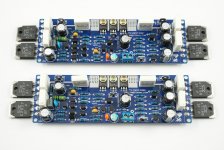
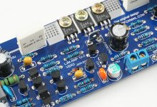
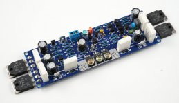
In China there are a lot of piracy L series power amplifier module. They have a plenty of red, or yellow, black.There are a few suppliers of these modules as kits of parts and in the past, they haven't all supplied the same Sanken transistors and power resistors. Perhaps there could be some variation in components because I can't provoke instability that can be seen on a 'scope either.
If I do find any little wriggles or bursts of oscillation on a trace, I simply fit a parallel LR of 1-2 uH and 6.8Ω in line with the flex to the output terminals. This is much the same as others suggest and has the benefit of not having to remove the PCB or affect the amplifier.
If you do nothing about this problem, it's just asking for repeat failures so restore ordinary twinflex for the cables. In fact, I can only see this cable as a weird reactive load and hardly a good idea when the supplier cannot know what speakers or amplifier it could be connected to, nor how it might affect them and the sound output. 😕
One thing is for sure. L12-2 has been using since birth
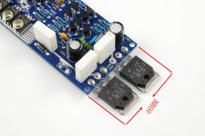
SANKEN LAPT 2SA1186 2SC2837.
It is probably the most rapid current transistor.
Can reduce the CFP, switch distortion.
L12-2 is a little change. Better performance.
But I don't think you need to pay attention to the output inductor, only when we use capacitor as a load, rather than drive speakers.
Inductor is needed.
Our power amplifier drive capacity, rather than the inductance, there's a possibility, at least I won't do that.
If you have a really like output inductor, capacitor load to driver.
Then a knife with a self-contained silk, with copper wire around the above 20 laps.
😛
Attachments

Ten turns of 0,5-1mm dia wire around 3W resistor of 1 to 10 Ohms value. The values are not critical, anything in this range will do.
If your amplifier is load capacitance, rather than speakers. The output end really need inductors.
, of course, also include this possibility: the length of the sound box line more than 20 meters in parallel, because the sound box line is too long can produce capacitor. Such as the application stage.
If it is a home, you don't need a inductance on the output side, it will increase the impedance.
😉
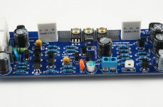
I notice the input capacitor is different ! What brand is that ?
Aliexpress.com : Acquista Samwha polimerico a semiconduttore di capacit oscon 25v33uf da Fornitori semiconduttori utilizza affidabili su LJM AUDIO DIY
😀
It 20 times smaller than the ordinary capacitance loss
So I should be able to order a few for myself from your site which isn't in English ! 🙂 Or do I go to Alibaba's global site ?
By the way I currently use my L12 amp without an input capacitor !It has a passive volume control ahead of it. Sounds great. Just connected it to a Emotiva-DC1 DAC and it sounds superb ! Thanks.
As usual the source is very critical to determine what the amp is capable of delivering !
By the way I currently use my L12 amp without an input capacitor !It has a passive volume control ahead of it. Sounds great. Just connected it to a Emotiva-DC1 DAC and it sounds superb ! Thanks.
As usual the source is very critical to determine what the amp is capable of delivering !
Last edited:
So I should be able to order a few for myself from your site which isn't in English ! 🙂 Or do I go to Alibaba's global site ?
By the way I currently use my L12 amp without an input capacitor !It has a passive volume control ahead of it. Sounds great. Just connected it to a Emotiva-DC1 DAC and it sounds superb ! Thanks.
As usual the source is very critical to determine what the amp is capable of delivering !
L12-2 Very good. I used to use it to assemble the machine, the use of single crystal copper transformer 500 va.
Huge radiator chassis. Such a machine I used to sell to customers a lot of Switzerland.
The price of more than $6000 each. 😀
My alibaba international website is still in the study.
More for a product introduction to foreign friends and show effect.
I also don't know much about cheap international postal service
🙁
Most of the time, L don't need to input capacitance series amplifier.
Such as L20SE L25. They have no input capacitors. The same is very stable and reliable.
Last edited:
Hi LJM_LJM
as you said there is lot of copy of this amplifier. Please could you send link where I can buy good quality L12-2 amplifier with latest revision. Seems it is R3. What do you recommend for Power Supply?
as you said there is lot of copy of this amplifier. Please could you send link where I can buy good quality L12-2 amplifier with latest revision. Seems it is R3. What do you recommend for Power Supply?
My live measurements
Hi All,
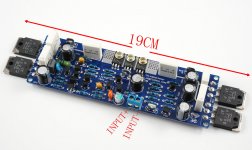
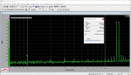
Just got a pair of the boards from ebay - measured the key parameters yesterday.
Power rails were +/-36V DC.
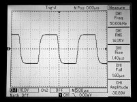
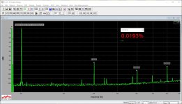
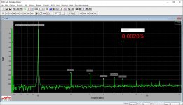
All the spectrums are measured at 20VRMS, 8 ohm resistive load - equal to 50W output. I can't go higher due to my load resistor power, rather hot already 🙂
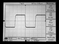
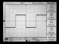
Square waves - 30V amplitude (p-p).
Very good performance, I must say
Cheers,
Valery
Hi All,
Just got a pair of the boards from ebay - measured the key parameters yesterday.
Power rails were +/-36V DC.
All the spectrums are measured at 20VRMS, 8 ohm resistive load - equal to 50W output. I can't go higher due to my load resistor power, rather hot already 🙂
Square waves - 30V amplitude (p-p).
Very good performance, I must say
Cheers,
Valery
Attachments
Hi Valery
Good that you have now received your modules. The results agree with what I tested using the Quantasylum QA 400 card and they are certainly good value. How hot did the supplied heatsink become when you tested to 50W?
Good that you have now received your modules. The results agree with what I tested using the Quantasylum QA 400 card and they are certainly good value. How hot did the supplied heatsink become when you tested to 50W?
Hi Valery
Good that you have now received your modules. The results agree with what I tested using the Quantasylum QA 400 card and they are certainly good value. How hot did the supplied heatsink become when you tested to 50W?
Hi Ian, the heatsinks were still pretty much ok - I would assume some 60-70 degrees, from what I felt with my hand, although they look somewhat smallish to me, especially thinking about potential capability of driving some 100W.
However, a 50W load resistor felt much more stressed at that time 😛
quick solution to heatsinks
Sorry to have been away from the forum and threads for various reasons.One of which is That I rebuilt my blown amplifier boards with replacement units .I have now used the two spare heatsinks by resting new stuff on top of older ones and wedging them tightish.
This is a very easy way to nearly double up the safety margin but Ive lost the benefit of air circulation.
I am now Using 53V rails (500VA)and having a pair of 86-87 DB sensitivity speakers in a huge room, so I still managed to blow the 3.15 fuse without the slow start setting board cutting the power off.
This has two thermal cutouts in the design/?.Now this was a little worrying but problem was caused by the sacd player.
I was just about to remove those HORRID SOUNDING Oscons which I have never been able to tolerate even in the power supply rails let alone in the signal path.Hope at Xmas I will get around to transferring all my vishays to the new boards.Then its No DC blocking cap.
If anyone is interested I do have a pile of spare bits from my original boards.Also started a grand parts clearance on ebay last week of BGs opamps vishays /drivers etc.(Guess why?)
HiHi Ian, the heatsinks were still pretty much ok - I would assume some 60-70 degrees, from what I felt with my hand, although they look somewhat smallish to me, especially thinking about potential capability of driving some 100W.
However, a 50W load resistor felt much more stressed at that time 😛
Sorry to have been away from the forum and threads for various reasons.One of which is That I rebuilt my blown amplifier boards with replacement units .I have now used the two spare heatsinks by resting new stuff on top of older ones and wedging them tightish.
This is a very easy way to nearly double up the safety margin but Ive lost the benefit of air circulation.
I am now Using 53V rails (500VA)and having a pair of 86-87 DB sensitivity speakers in a huge room, so I still managed to blow the 3.15 fuse without the slow start setting board cutting the power off.
This has two thermal cutouts in the design/?.Now this was a little worrying but problem was caused by the sacd player.
I was just about to remove those HORRID SOUNDING Oscons which I have never been able to tolerate even in the power supply rails let alone in the signal path.Hope at Xmas I will get around to transferring all my vishays to the new boards.Then its No DC blocking cap.
If anyone is interested I do have a pile of spare bits from my original boards.Also started a grand parts clearance on ebay last week of BGs opamps vishays /drivers etc.(Guess why?)
Hi All,
Just got a pair of the boards from ebay - measured the key parameters yesterday.
Power rails were +/-36V DC.
All the spectrums are measured at 20VRMS, 8 ohm resistive load - equal to 50W output. I can't go higher due to my load resistor power, rather hot already 🙂
Square waves - 30V amplitude (p-p).
Very good performance, I must say
Cheers,
Valery
Hi Valery.
Can you advise which eBay seller you got these from? Thanks
Hi Valery.
Can you advise which eBay seller you got these from? Thanks
Hi, here is the link to the particular item from the seller I've got it from:
L12 2 Power Amplifier 2 CH Assembled Boards Heatsinks | eBay
Seller: along1986090
Cheers,
Valery
Ebay purchases
Well folks I have purchased Five of these cheap boards from Lazerlands China
and they look identical to "along" however 4 of these boards have now failed in normal use.
The first pair were possibly because of my transformer fault and it was easier cheaper to just reorder. New Traffo now.
One of the two arrived faulty and was clearly a dry joint.Worked ok after resoldering the output devices.Seller notified.
Sadly that board failed after a couple of weeks and by then I had swapped some vishays into it. Identical value.
This board was replaced last week with another new board. Which only lasted 3 days.
I am off on hols again so will sort it out when I return.After all I have plenty of replacement parts now, Will let you know which items went but their was that distinct smell just after switching off .

I also made a note that the board changes character after a short while and loses some of its bloom.
If this was a parachute I would suggest you stay in the plane. ?
The alternative amplifier is working ok and I have double the normal heatsinking than suggested.
Dave
Well folks I have purchased Five of these cheap boards from Lazerlands China
and they look identical to "along" however 4 of these boards have now failed in normal use.
The first pair were possibly because of my transformer fault and it was easier cheaper to just reorder. New Traffo now.
One of the two arrived faulty and was clearly a dry joint.Worked ok after resoldering the output devices.Seller notified.
Sadly that board failed after a couple of weeks and by then I had swapped some vishays into it. Identical value.
This board was replaced last week with another new board. Which only lasted 3 days.
I am off on hols again so will sort it out when I return.After all I have plenty of replacement parts now, Will let you know which items went but their was that distinct smell just after switching off .
I also made a note that the board changes character after a short while and loses some of its bloom.
If this was a parachute I would suggest you stay in the plane. ?
The alternative amplifier is working ok and I have double the normal heatsinking than suggested.
Dave
That's an awful experience - something I haven't heard of with this design before. It seems clear that Lazerlands is not supplying genuine components and uses unreliable assembly and test methods.
However, what are you referring to by: " that board failed after a couple of weeks and by then I had swapped some vishays into it. Identical value."
However, what are you referring to by: " that board failed after a couple of weeks and by then I had swapped some vishays into it. Identical value."
Board failures
Hi Ian
Basically ,after I had installed the ready made boards, I did not think the metal film resistors were good enough for the sonics that can be tweaked from this circuit, so replaced approx 40 with Vishay bulk foils 1 percent)
(I have spent nearly 50 years modifying electronics)
I had also previously altered the first pair of boards with4 x Elna Silmics to nice effect.Addition heat sinking on outputs had no sonic effect.
Will report on exactly what has failed on each board to date but obviously once you modify a board you have no comeback with the supplier.Even though they had faults when supplied.(soldering)
The only significance was the board failed whilst switching off after an hours listening and their was no sign of overheating.
A protection circuit is installed.
I am off on holiday for a weeks warmth and dryness in less that 24 hours so time is a bit limited at the moment .
Dave
A quick visual/measurement check reveals ..R8 100R overheated burnt R23 R100 same and also R19 in between very slight burn ? but measured open circuit.
Is this bias circuit ?
I measured impedance on legs of Q8 Q7 and seem ok Q12 measures different but same as other board.Pressume its ok.
Only commnent is that resistors burnt seem very close to circuit board.(Over heat?)
Neither of these problems were similair to previous faults.ie pair output drivers failed? and unknown fault on board 4.
Hope to have time to replace but off at 2am in the morning.
- Home
- Amplifiers
- Solid State
- L12-2 CFP Output amp 120W*2 8R