I don't use impedance compensation if there's a natural way around it, and there often is. This means I do use it whenever the nature of a peak is beyond the capability of a regular filter to fix.Something AllenB said in the "Introduction to designing crossovers without measurement" thread (IDCWM thread next time) indicated that impedance could be dealt with in the crossover itself and I thought his wording carried the hint that a better sound could be got that way.
Compression driver resonance double peaks are an example of where I do use impedance compensation. I use tuned circuits for this. The parallel resistor method is simpler and I sometimes use it, but the RLC circuits are more targeted and you get more smoothing with less reduction in impedance. I recommend you use perhaps two on your tweeters if you can't manage to deal with the impedance peaks translating into response peaks.
I don't agree that they sound better or worse if you design properly. When people tell me they do, I ask them whether the response changed when they added it because that's what they are hearing. Not so for us, since we are aiming for the same correct response regardless.
The resonance behaves like it's own resistor/inductor/capacitor, even though they are only equivalents.Not quite sure how to read your comment on 120Hz & Fs
Last edited:
Indeed.The horn was recommended by Pano for higher frequency fill use
My concern with your intended use is that I would try not to use it below 3kHz, which limits me to using it with nothing larger than a 7" woofer.
On the other hand I'm sure that many use it much lower and have no complaints.
For the driver, on the other hand, I feel the same as Stanislav
The TAD can comfortably play at around 1khz but with a different horn.
Is that regardless of whether you are padding down a more sensitive tweeter. (Just thinking of the L-pad circuit in XO image above)I aim for less than 5% of the tweeter Re
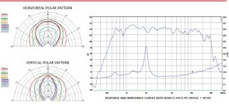
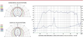
I looked at the data sheets for the H225 and H250 but couldn't really figure out why you might choose one over the other. It looks like the biggest difference in the polars is in the vertical pattern. Also in the FR the general impression is that H225 trace has negative peaks and the H250's peaks are positive, though I somehow doubt you look at it that way.Try the SB Acoustics horn,
Attachments
Do you have any recommendation for reading material on doing that with RLC networks specifically ?I recommend you use perhaps two on your tweeters
My question was really more about proximity. I didn't understand why you were concerned with a 120Hz peak when the driver's are at 400 and 1Khz..The resonance behaves like it's own resistor/inductor/capacitor
My concern with your intended use is that I would try not to use it below 3kHz. . . .
. . . . . For the driver, on the other hand, I feel the same as Stanislav
The TAD can comfortably play at around 1khz but with a different horn.
I have often seen recommendations for using a horn with cutoff well below it's intended range. In this case a horn with 600Hz cutoff for a driver that can only go down to 800Hz. On the other hand, my understanding is that the dimension of the horn dictates the highest frequency that can be produced before beaming . So I guess my question is, When choosing the horn, why the deference to the bottom end and not the top?
If I could take a step back and put it another way.. if you are trying to identify one source of inductance such as the coil inductance, and in this case separate it from the coil resistance, you should get the same result from two different frequencies. Otherwise it could be that there are reactances from other sources affecting one or more of those frequencies. (It's also possible that a measuring tool behaves inconsistently vs frequency.)My question was really more about proximity. I didn't understand why you were concerned with a 120Hz peak when the driver's are at 400 and 1Khz..
If you can post an impedance plot, and remember that it changes on a horn, I wouldn't mind starting the process.Do you have any recommendation for reading material on doing that with RLC networks specifically ?
Cutoff is not particularly relevant to domestic tweeter use because it's about radiation efficiency and you shouldn't have a problem with output capability.I have often seen recommendations for using a horn with cutoff well below it's intended range. In this case a horn with 600Hz cutoff for a driver that can only go down to 800Hz.
It tells you nothing about the shape of the horn or the size of the horn. It doesn't tell you how low it can be used because I can mount a direct radiating woofer behind a 19mm baffle, use a router to shave it to the right angle and call it a 100Hz cutoff horn, but it won't have any realistic capability.
If you want to control output directivity, what matters is the size and shape.
I've heard this before, I wonder where it comes from. It sounds like what is said about direct radiators. Beaming is an often misunderstood term. Some people are not certain whether it's good, bad or neither.my understanding is that the dimension of the horn dictates the highest frequency that can be produced before beaming .
Higher frequencies are usually determined near the throat. Lower frequencies are more affected by the angles and mouth size. In this horn, the vertical (height) is both shorter and more narrow, which tends to set the limit on how low it will perform as expected.
I usually have a rule of inductor DCR < 10% of driver Re in any filter. There's some info about that in the Loudspeaker Design Cookbook. I do go to 5% for that series inductor to protect the tweeter.
I'm finding out that the LCR meter in Clio can only measure DCR of a non-inductive element . Otherwise it is giving reactance and that at frequencies it chooses , no generator control for the user with LCR meter function , so it tests different things at different frequencies. and its reactace measurement in LCR meter doesn't line up with what it measures in the impedance vs frequency window, which I gather is probably accurate.if you are trying to identify one source of inductance such as the coil inductance
The DVM gives 5.7Ω for Re.
On the horn or off?If you can post an impedance plot,
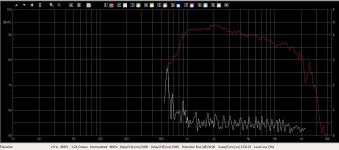
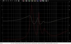
Edit : posted are plots with horn . FIrst is Frequency Response, Second is Impedance and phase, Third is Impedance and with 15 Ohm R parallel.
These were done before. I'm happy to redo them if you want parameters changed in any way.
Well, maybe I'm using the wrong word, I'd heard that and thought it was what is being shown in polar plots (such as in the ones for SB Acoustics linked above in #63 ) where the higher the frequency the narrower it gets.I've heard this before,
I had this idea that smaller horns did better at high frequency dispersion than larger ones.
Attachments
Last edited:
Normally you'd do it on the horn but I'll take whatever you have there to offer for demonstration.On the horn or off?
If it gives you reactance rather than impedance and if you know the frequency and it's in the upper octaves then you can calculate the inductance.it is giving reactance and that at frequencies it chooses
L = XL/(2*π*f)
I tried that and it's . . . . . crazy. Trying together with figures from the Extech LCR and using an online calculator for speed nothing correlates. I'll go after it again tomorrow.If it gives you reactance
Just added them to the post above while you were posting .Normally you'd do it on the horn
"posted are plots with horn . First is Frequency Response, Second is Impedance and phase, Third is Impedance and with 15 Ohm R parallel.
These were done before. I'm happy to redo them if you want parameters changed in any way. or if you want them in txt or whatever."
Thanks
Not necessarily on a waveguide, it's more consistent. However some waveguides are significantly curved along their length. It's good for smooth termination, not so good for directivity unless they're also larger.I had this idea that smaller horns did better at high frequency dispersion than larger ones.
Horns have a tendency to flare in ways that sometimes make the highs more narrow. There are too many factors to say without looking at the one in question.
I'll take a look.Just added them to the post above while you were posting .
You're welcome.
This may be more complicated than necessary, you can try just parts of it, change their levels, whatever works..

This may be more complicated than necessary, you can try just parts of it, change their levels, whatever works..
Yes, it all looks flash and dandy but it's only suitable for parallel networks. Try it in a series xo and you'll be unpleasantly surprised. And gets even worse with higher orders, 2nd, 3rd and so on.
So maybe best to abandon the series xo idea and go full parallel. Prepare to need to introduce even more compensating networks. Or select other drivers that will work better with a 1st order series xo.
Me, being comfortable with series networks and their shortcomings, I know which way I'll go.
So maybe best to abandon the series xo idea and go full parallel. Prepare to need to introduce even more compensating networks. Or select other drivers that will work better with a 1st order series xo.
Me, being comfortable with series networks and their shortcomings, I know which way I'll go.
It just occurs to me that I'm discussing this on three or more threads and hope I'm not posting on the wrong ones 😀
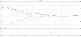
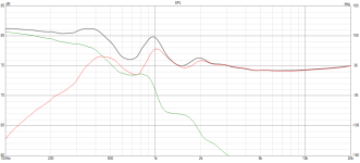
Stanislav, I agree that the series crossover can reduce variations due to impedance variations and may possibly not be necessary, especially for example as with some inexpensive commercial speakers where the tweeter resonance boosts the output for the woofer in the reduced power top end, and a couple of other things.
However if what we do is deliberate.. take this example of a series crossover with 6dB of series tweeter attenuation (the smoother one is with compensation)


hope I'm not posting on the wrong ones 😀
Nope, you're right on target. And thank you. The point for me though is to understand the process.
So far what I think I see is that you start with the centre frequency of each impedance peak. Then estimate the parallel resistance that will level the impedance at that frequency. Then calculate values of L and C to get a resonant circuit that goes purely resistive at that centre frequency and is the same Q as the entire peak.
Have I got that right? and if so, are those the right steps
I have to say , I do like the basic character of this thing .Me, being comfortable with series networks and their shortcomings, I know which way I'll go.
. . . . . . No comment on the difference between SB horns ?
More or less, yes. You'll pick it up in no time.are those the right steps?
More or less, yes. You'll pick it up in no time.
I've heard that line before. 😀 At first it's comforting/confidence inspiring until you dip your toes into the water. A keyhole looks small enough. Looking through it though reveals a rather larger picture.
Thanks AllenB
By the way, I found this calculator last night. (For Series RLC Resonant Circuits) Very nicely done.
- Home
- Loudspeakers
- Multi-Way
- L-Pad on Series Crossover?
