It seems to me that l-pad in tweeter section is not a good idea. It is effectively shorting the inductance of the crossover coil and the tweeters inductance, thus changing the crossover point. Threads i found were not of help. Any definite solution? Just one resistor in parallel with tweeter?
Hi,
The point of an L-pad is it presents the same
impedance as the driver no matter the setting.
They work just fine in series crossovers.
I cannot see the problem you imagine.
The single parallel resistor is the bad idea.
No volume change and a shift in x/o point.
rgds, sreten.
The point of an L-pad is it presents the same
impedance as the driver no matter the setting.
They work just fine in series crossovers.
I cannot see the problem you imagine.
The single parallel resistor is the bad idea.
No volume change and a shift in x/o point.
rgds, sreten.
Last edited:
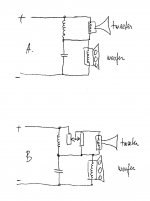
If I read your blog correctly, you're using the '75 chip amp in current output config (transconductance amp) to drive the mids & tw and assuming the Xover has been built as a series filter (the current passes thru the tweeter and mid in series) so any attenuator needs to be setup as a current diving network unlike the usual way of attenuating the tweeter - L-pads aren't really a good way of doing this despite the supposed simplicity
In practice, it's usually easier to start with the amount you want to attenuate the tweeter and apply the bypass resistor across the tweeter terminals that acts as a current divider, hence attenuates the tweeter volume - as this will reduce the series impedance that the Xover sees, will need to add the equivalent resistance in series with the tweeter/bypass combination - it's a bit of a juggling act and I find it's better to just adjust the Xover components to suit the reduced impedance of the tweeter/bypass combination - current drive is a bit different to the usual approach to Xover design -
Oh yes, you need to use good quality resistors that'll take the full current load - suggest avoiding metal oxides, so try metal film like Caddocks, etc, non inductive wirewound like Mills, etc as the bypass resistor will directly effect the sound.
Looking at your Blogs, not sure if you're attenuating the 'Ribbon & dome tw + dual 6" mids' pair or the other setup with the neo3 + Fostex125 + Pioneer 6" - either one is going to present a bit of a challenge to the series Xrossover and the final levels are probably easier to achieve by the old 'trial & error' way as I think you'll have quite a variation in impedance across the freq range but surprisingly, you'll possibly find this aspect isn't as critical with the current drive amp.
The FIrst Watt papers have a good description about this.
Your gallery of speakers takes me down memory lane - I lost considerable amounts of hair trying to sort out the Onkyo Sceptre speakers - never did get them quite right.
In practice, it's usually easier to start with the amount you want to attenuate the tweeter and apply the bypass resistor across the tweeter terminals that acts as a current divider, hence attenuates the tweeter volume - as this will reduce the series impedance that the Xover sees, will need to add the equivalent resistance in series with the tweeter/bypass combination - it's a bit of a juggling act and I find it's better to just adjust the Xover components to suit the reduced impedance of the tweeter/bypass combination - current drive is a bit different to the usual approach to Xover design -
Hi,
If you don't tweak the x/o components its just a standard L-pad.
Current drive is not that much different, an L-pad doesn't care.
rgds, sreten.
Additionally, you can use an L-pad to increase the apparent tweeter impedance and lower the output at the same time. There are physical limits to when and by how much you can do this, but I've for instance taken a 3.6 Ohm tweeter and made it an 8-ish one while padding the output a few dB. I did waste a little extra wattage in the resistors, but the amp was less loaded so a good deal I think.
I'll just throw in some unusual series crossover topologies that are worth investigating IMO. Including a 3 way.
Firstly series crossovers need well-behaved drivers. Polycone basses, flat mids and robust and loud tweeters. Because you are limited in your options and forced to shallow filters.
Within that, you can bring to bear a lot of good techniques like impedance flattening and Zobel networks along with straight attenuation. Some series filters include hidden goodies like natural Fs and breakup notches. Hence the flat slopes.
How it turns out is up to you, but all these three unusual styles are interesting IMO. It's the hobby. 🙂
Attachments
A single series resistor after the crossover can also be beneficial by tilting the response downward, etc...that's why modelling is important.
Ok, maybe I am just paranoid, but I see a problem with L-pad in series crossover. Or I am just wrong. So here we go again. What I am doing right now is trying to find out if square wave perfect series crossover is going to sound better than typical parallel crossover.
I have few projects where 2-way speakers are perfectly working with optimized parallel crossover. For instance, 12" coaxial B&C, or small bookshelf AC130F1 and Fountek ribbon tweether...in each case tweeter more efficient then midwoofer. Take the B&C coax, I use simple 4 uF cap on the tweeter, 0.25mH inductor on the woofer, and since tweeter is horloaded, its more efficient, so I use L-pad. No problem, it measures and sounds great. Now I want to convert it to series crossover. I am looking at it and it seems the L-pad is parallel to the coils which determines woofers rollof. Now the tweeter is in reality a inductor too, as it has significant inductance, and resistance. But the L-pad is just the resistor. Isn't the resistor in parallel with inductor going to make shelving filter? The same would happen with capacitor if resistor is placed in parallel to it.
I have few projects where 2-way speakers are perfectly working with optimized parallel crossover. For instance, 12" coaxial B&C, or small bookshelf AC130F1 and Fountek ribbon tweether...in each case tweeter more efficient then midwoofer. Take the B&C coax, I use simple 4 uF cap on the tweeter, 0.25mH inductor on the woofer, and since tweeter is horloaded, its more efficient, so I use L-pad. No problem, it measures and sounds great. Now I want to convert it to series crossover. I am looking at it and it seems the L-pad is parallel to the coils which determines woofers rollof. Now the tweeter is in reality a inductor too, as it has significant inductance, and resistance. But the L-pad is just the resistor. Isn't the resistor in parallel with inductor going to make shelving filter? The same would happen with capacitor if resistor is placed in parallel to it.
Attachments
Um, dear god's man. Stop paper drawing. Get XSim. Simulate your crossover. Click:
Add Graph
more ->
Square Wave Response
Questions answered. 🙂
Best,
Erik
Add Graph
more ->
Square Wave Response
Questions answered. 🙂
Best,
Erik
Ok, maybe I am just paranoid, but I see a problem with L-pad in series crossover. Or I am just wrong. So here we go again. What I am doing right now is trying to find out if square wave perfect series crossover is going to sound better than typical parallel crossover.
I have few projects where 2-way speakers are perfectly working with optimized parallel crossover. For instance, 12" coaxial B&C, or small bookshelf AC130F1 and Fountek ribbon tweether...in each case tweeter more efficient then midwoofer. Take the B&C coax, I use simple 4 uF cap on the tweeter, 0.25mH inductor on the woofer, and since tweeter is horloaded, its more efficient, so I use L-pad. No problem, it measures and sounds great. Now I want to convert it to series crossover. I am looking at it and it seems the L-pad is parallel to the coils which determines woofers rollof. Now the tweeter is in reality a inductor too, as it has significant inductance, and resistance. But the L-pad is just the resistor. Isn't the resistor in parallel with inductor going to make shelving filter? The same would happen with capacitor if resistor is placed in parallel to it.
Hi,
Simple fact is you can treat any L-pad connected driver
as simply an 8 ohm driver (in reality its not so simple)
and it simply makes no difference to series or parallel.
In reality there is a real difference between 1st order
series and 1st order parallel. Bass unit inductance
helps series but fights parallel. Tweeter impedance
peaks help series but fight parallel relatively spaaking.
YMMV but unless you want offset first order crossover
points, generally first order series is the best option.
rgds, sreten.
If you have a clear goal, there's no reason you couldn't achieve it either way. Remaining differences between a spot on parallel and series crossover would be parasitic/superficial and even these points can be addressed.
The common benefit claimed for a series crossover is the fortunate interaction of the practical elements.. varying degrees of imperfection. A way to get a good result from a limited set of components.
In a series crossover the drivers appear in parallel to the output of the filter. The tweeter impedance peak occurs where the woofer impedance is low. The woofer impedance rise appears where the tweeter impedance is low.. by and large.. so it can be exploited. Work on these either way and the line between the two crossover types disappears.
Yes, the L-Pad throws this, it is what it is. A disadvantage to the series crossover is the complexity in navigating the interactions when making crossover changes by ear.
I read an interview with John DeVore, he of the famous Orangutan Speaker, who is a bit of a natural, IMO. Maybe you can find it.
He often likes putting the bass on top of the tweeter, because he just feels it is more natural. He also claims to use no resistors at all in crossovers.
That's easy for him with complete control of manufacturing. 🙂
As we know, all tweeters with a voicecoil have inductance. You can actually reduce inductance considerably with SB acoustics type copper shunting rings in the voicecoil gap and the like. AMT types are resistively flat, which might be a good thing.
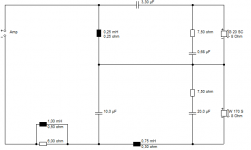
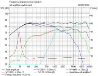
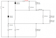
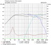
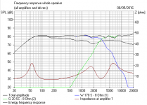
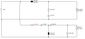
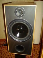
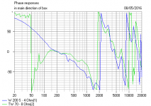
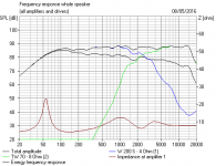
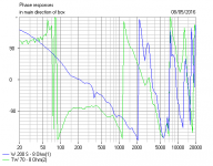
Let's look at the WLM La Scala, which uses these paper drivers;
W 200 S - 4 Ohm
TW 70 - 8 Ohm
It's a weird combination because the W200S-4 ohm has a horrible bump at 3.5kHz, but it all just happens to play very nicely together on a near LR2 series crossover. So it works, IMO. I fancied some top end Impedance Correction here, for the amp friendliness, so I shunted a Joe Rasmussen-style near tweeter Zobel 9.1R and 2.2uF across the whole filter too for the final plot.
TBH, I don't much focus on lively transient perfect, preferring steeper low-distortion BW3 filters like the second lot. It's just one of the many factors. But both circuits have their strengths IMO.
There's many ways to skin a cat, IMO. 🙂
He often likes putting the bass on top of the tweeter, because he just feels it is more natural. He also claims to use no resistors at all in crossovers.
That's easy for him with complete control of manufacturing. 🙂
As we know, all tweeters with a voicecoil have inductance. You can actually reduce inductance considerably with SB acoustics type copper shunting rings in the voicecoil gap and the like. AMT types are resistively flat, which might be a good thing.
Let's look at the WLM La Scala, which uses these paper drivers;
W 200 S - 4 Ohm
TW 70 - 8 Ohm
It's a weird combination because the W200S-4 ohm has a horrible bump at 3.5kHz, but it all just happens to play very nicely together on a near LR2 series crossover. So it works, IMO. I fancied some top end Impedance Correction here, for the amp friendliness, so I shunted a Joe Rasmussen-style near tweeter Zobel 9.1R and 2.2uF across the whole filter too for the final plot.
TBH, I don't much focus on lively transient perfect, preferring steeper low-distortion BW3 filters like the second lot. It's just one of the many factors. But both circuits have their strengths IMO.
There's many ways to skin a cat, IMO. 🙂
Attachments
-
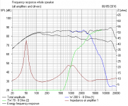 WLM La Scala style Parallel FR.PNG21.8 KB · Views: 224
 -
 WLM La Scala Parallel Circuit.PNG7.2 KB · Views: 447
 -
 WLM La Scala.JPG26.7 KB · Views: 455
 -
 WLM La Scala Series Phase.PNG23.3 KB · Views: 436
 -
 WLM La Scala Series FR.PNG19.5 KB · Views: 448
 -
 WLM La Scala Series 1.PNG7.5 KB · Views: 469
 -
 WLM La Scala Parallel Phase BW3.PNG27.8 KB · Views: 162
Last edited:
Here is what I am after...
Series vs. Parallel Crossover Networks
But I see that I am misunderstood being the only one seeing that parallel and series would be the same in theory, but once I put the L-pad in the crossover, series crossover is affected, parallel is not. I would like to have the same speaker done with both crossovers, and throw 1k Hz square wave on it, and see if it measures differently, and if it does, if it sounds differently. But that L-pad in parallel with inductor is messing my head.
I think I will select different drivers, where midbass and tweeter are closely matched with sensitivity and do the experiment.
These impedance variations which the series crossover shows immunity toward, are of course dealt with in a parallel crossover. How then if you want to tailor the drivers separately in a series crossover, than to nest a separate parallel style network section between the series crossover and the driver to defeat this inter-dependence. Take it where you want to, if you take my drift.
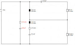
I don't tend to put series resistors in the tweeter block on the SXO layout. It should go in this manner:
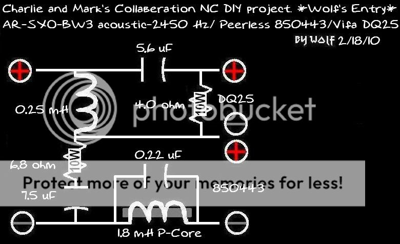
The 6.8 ohm is the series resistor attenuation for the tweeter.
Cascaded 3-way example:
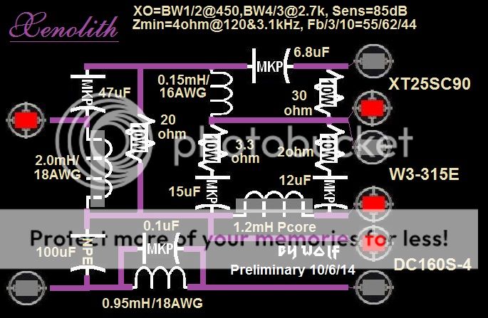
In discussion of using an actual L-pad in an SXO, I did come up with a method:
http://techtalk.parts-express.com/filedata/fetch?id=1146971
Hope that helps your journey...
Wolf

The 6.8 ohm is the series resistor attenuation for the tweeter.
Cascaded 3-way example:

In discussion of using an actual L-pad in an SXO, I did come up with a method:
http://techtalk.parts-express.com/filedata/fetch?id=1146971
Hope that helps your journey...
Wolf
but once I put the L-pad in the crossover,
series crossover is affected, parallel is not.
Hi, Not true, the L-pad makes no difference to either, rgds, sreten.
You really need to illustrate your apparent concern, as it is wrong.
Last edited:
The idea of an L-pad is that it reduces the voltage going to the driver without changing the impedance presented to the rest of the crossover therefore the L-pad is totally invisible to the rest of the crossover as opposed to simply adding a series resistor to the driver. That is why in an L-pad there is a resistor across the driver - it reduces the overall (L-pad and driver) impedance to compensate for the series resistor raising it. The resistors work together to provide the attenuation - reducing the parallel resistance or increasing the series resistance will increase attenuation however there is only one combination of resistances for a given attenuation that give a total impedance that is the same as the driver.Here is what I am after...
Series vs. Parallel Crossover Networks
But I see that I am misunderstood being the only one seeing that parallel and series would be the same in theory, but once I put the L-pad in the crossover, series crossover is affected, parallel is not. I would like to have the same speaker done with both crossovers, and throw 1k Hz square wave on it, and see if it measures differently, and if it does, if it sounds differently. But that L-pad in parallel with inductor is messing my head.
The only problem remaining is that an L-pad assumes that the driver is resistive (same impedance at every frequency) and most drivers are not - they have a peak at low frequency due to their mechanical resonance and a steady increase at high frequency due to the voice coil inductance. This means in order to have an L-pad that both attenuates a speaker evenly across the entire frequency range and produces produces the same impedance regardless of the amount of attenuation the driver must have impedance flattening (zobel) filters added to it. Leaving out the zobel presents problems for both series and parallel crossovers.
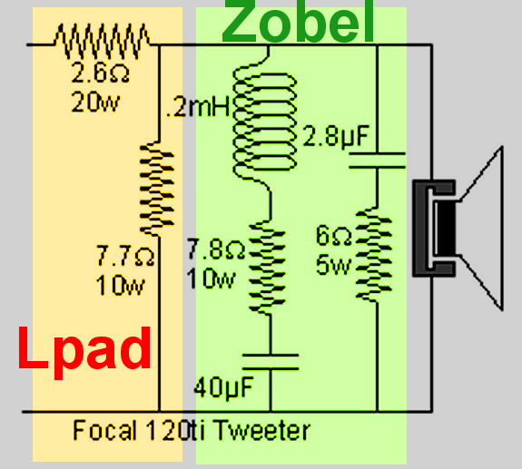
The inductor-resistor-capacitor combination flattens the peak due to the mechanical resonance of the driver, the capacitor-resistor flattens the voice coil rise.
example of flattening the impedance of a driver using zobels:
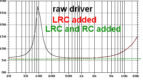
Some times it is only necessary to flatten the impedance as much as needed to make the crossover behave. For instance there is no need to flatten the voice coil rise of a tweeter that only appreciably rises above 20kHz, or flatten a 50Hz mechanical resonance of a driver being high-passed at 800Hz.
Last edited:
- Status
- Not open for further replies.
- Home
- Loudspeakers
- Multi-Way
- L-pad in series crossover