Wire diameter is 2x 0.85mm (solid wire) and the length is about 35cmWhat wire gauge you use and how long? (Towards the Rpi4)
Attachments
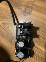
Was there a problem with RPi4 always occurring or it developed? Looks like there's also a shielding braid. Is it attached to zero on the other end?
Did you see any weird AC waveform or bad noise issue on the scope during the DC out level change?
Where you have been scoping? At the L-Adapter's end or at the RPi's end?
Did you see any weird AC waveform or bad noise issue on the scope during the DC out level change?
Where you have been scoping? At the L-Adapter's end or at the RPi's end?
Not a low secondary or too much ripple issue as it shows. Some basic culprit would be an erratic trimmer or a dodgy connector at the RPi.Hello,
The voltage drop is around 8.2-8.3V. 13.47V on one side, and around 5.2V on the other side. And not changing significantly when the stability issue are there
I’ve sent a link from the measurement in a private messageWas there a problem with RPi4 always occurring or it developed? Looks like there's also a shielding braid. Is it attached to zero on the other end?
Did you see any weird AC waveform or bad noise issue on the scope during the DC out level change?
Where you have been scoping? At the L-Adapter's end or at the RPi's end?
Yep, just saw it. Long video, can't be uploaded here. Anyway, in all its length there are no suspicious AC oscillations or noise bursts captured, but clean DC level shifts.
Scope's probe was at the L-A output end?
Lets also do few small voltage checks to see if the semiconductors are good.
Scope's probe was at the L-A output end?
Lets also do few small voltage checks to see if the semiconductors are good.
R2 voltage drop 0.073V (5.86V-5.79V)Voltage across legs of R2, then across R3.
Vbe (base to emitter voltage) of Q1, then Q2.
R3 voltage drop 0.61V (13.25V-12.64V)
Vbe Q1=Q2=0.6V
Those spot voltages look normal. R2 drop shall remain constant in all load circumstances. Vbe voltages should grow a bit with heavier loading. Try with a different output cable and/or RPi4 connector maybe.
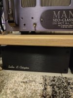
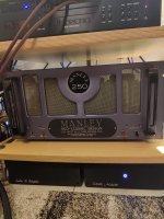
A couple more L-adapters, one for the 8 volt supply on my, still after many years, brutal Shigaclone cd player (the other is a Reflektor) and a 19 volt supply for my NUC i3 pc, doing playback duties with foobar.
I can say unexpected improvement of my digital playback. More depth, naturalness and a sense of less digital glare. It seems easier to listen to digital for longer, which was not easy for me, spoiled by my LPs.


I can say unexpected improvement of my digital playback. More depth, naturalness and a sense of less digital glare. It seems easier to listen to digital for longer, which was not easy for me, spoiled by my LPs.

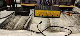
I decided to build one more L-adapter,after having two more(one for my Raspberry pi 4with volumio,and one for my Logitech squeezebox touch),for my dynavector dv 500 turntable, which is a well tempered Amadeus GTA with dynavector dv507 mk2 tonearm.i wasn't expecting so much improvement,I already had an lm317 linear psu.i was wrong.more black background,less grainy sound.thanks Mr Salas!
Attachments

@Salas what are these L-adapter PSRR numbers? If I like to use this L-adaptor as a current shunt for 310-340mA for the tube heaters then I just put jumper to the right place or I also have to do something else?
I see that MJE15030G is hard to get. What would be the good replacement for that?
Anybody have PCB-s to offer in EU?
I see that MJE15030G is hard to get. What would be the good replacement for that?
Anybody have PCB-s to offer in EU?
I found some answers. I did not saw L-adaptor guide at first look. PSRR -70dB or less 10Hz to 100kHz.
Jumper are used to set right voltage range and VR1 to trim it more. For the current do I use R2? How to set current for 330mA?
LM334Z is also very hard to find. Any replacement?
Jumper are used to set right voltage range and VR1 to trim it more. For the current do I use R2? How to set current for 330mA?
LM334Z is also very hard to find. Any replacement?
Its not a CCSed shunt PSU. Its a series PSU. Imagine it applied like a huge LM317.
R2 biases the voltage ref's CCS LM chip. Nothing for the user to directly set there.
LM334Z is to be restocked in major sellers. Meantime they got preciser wider temp versions of it:
Check out the LM234Z-3 and LM234Z-6. Being better in spec they are also more expensive.
R2 biases the voltage ref's CCS LM chip. Nothing for the user to directly set there.
LM334Z is to be restocked in major sellers. Meantime they got preciser wider temp versions of it:
Check out the LM234Z-3 and LM234Z-6. Being better in spec they are also more expensive.
Thank you for the reply! I am also just learning. Is it also possible to add this current regulation to this schematic? What changes I have to do?
No its not readily possible. For 330mA my Ultrabib V1.3 can do the job you are looking for. Its a CCSed shunt reg.
Ive been using a couple l-adapters for various 12-15v needs with great success. (Thank you!!) The other day I tried to replace the smps brick on my NUC i3. The smps has a rating of 19v/4.7A. The NUC runs just fine on 18V so I picked an 18V transformer. The transformer is 100VA, which is less than the 1.5x suggested in the guide but long term tracking showed that the NUC never goes above 10% CPU load shuffling music files around so I didn't figure I really needed more than 5A from the transformer. (I probably should have just directly measured it but I was being lazy)
Anyway, I'm getting nearly 27V after rectification. Which means I'm burning off more than 7V. I've got the heat down to a steady 36C. but it took a lot of sinking to get there. Far more sinking than what is needed at 15V.
Just wondering if all of this heat is normal or if I miscalculated something along the way?
The guide says to stay >2.5V difference but "not much higher". What would be considered "much higher"?
Thanks!
- Home
- Amplifiers
- Power Supplies
- L-Adapter