Thanks for the quick responce. Now I got it all right and my clone is working. I did a small fail at the PCB and did put the LM334 the wrong way. I used yellow leds and they seems to drift more than what others seem to have, so i will try others. Will try the ones I used in shunt reg project.
Attachments
It could be partly due to the different layout too. Try red Leds. You may also try increase the 12 Ohm value up to double if it helps to reduce their drift in your example.
Yes I was testing with an external dc-source to minimize problem sources. I have now tested with rectifying circuit and red leds and all is better. Actually really good. Improving my Allo Digione Signature hat some steps.
I now run with an Lifepo4 2s 2100mAh on the clean side. I may try to replace it with an Ultra bib later. Any thoughts about that?
I now run with an Lifepo4 2s 2100mAh on the clean side. I may try to replace it with an Ultra bib later. Any thoughts about that?
All well then. Nice that it also improved your sound.
I don't know about that clean side, it depends on the client circuit's priority sensitivities. Zo vs floating isolation for instance. You got to try and see which one solution sounds better to you there I guess.
I don't know about that clean side, it depends on the client circuit's priority sensitivities. Zo vs floating isolation for instance. You got to try and see which one solution sounds better to you there I guess.
Thanks for reply. The clean side of Digione Signature needs anything from 5 to 10volts >100mA. The most important is clean power. I will try a Ultra bib configured for 5volts and 100mA. Probably is battery feed hard to beat. But if you can skip the charging part now and then it would be nice. Maybe both alternatives will be a good solution.

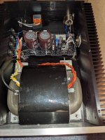
Congratulations. Substantial sinking and big R-Core I see. A heavy duty DIY PSU build for computer.
Horse race track shape transformer and a coin to mount power transistor states DIY made in Japan.
Nice to know it clearly bettered your perceived sound. Even over other linear PSU not just NUC SMPS.
Horse race track shape transformer and a coin to mount power transistor states DIY made in Japan.
Nice to know it clearly bettered your perceived sound. Even over other linear PSU not just NUC SMPS.
Your NUC can pull 90W continuously if you throttle it but normal programs don't push it there. Brief peaks. So heat does not build up on the large sinks. Unless you will play intense computer games.
I have tested with ACA mini and it was amazing.I can not forget.
Now I want to build another one.
Now I want to build another one.
can we use Mosfet instead of Bipolar? will it be stable for longer lengths of output wire. What are all the things to consider when we use Mosfet at the output?- We many times wonder what if that SMPS brick that feeds the Raspberry Pi or the mini PC or the MiniDSP or the Squeezebox or the DAC or the desktop Class-D amp etc. was a linear PSU? How such wonder boxes would perform without switching noise polluting their rail and most crucially their many times interconnected ground?
- What if we had a simple and strong linear PSU instead of fixed SMPS brick adapters that it could cover the voltage range for such applications by only setting it up with a jumper?
- Enter the L-Adapter. A versatile Sziklai pair stabilizer / capacitance multiplier based on LED voltage reference.
- Its output voltage is how many LED + trimmer minus one Vbe. Roughly 1.5V to 20V range. Move the jumper, trim Vout, ready. Connect the load.
- Is it any good? Yes its good. Not noisy at all and stable. For 1.5V input ripple it produces 1.5mV thick DC line. For 3 Ampere load it measures 0.02Ω output impedance. Which is flat and extended in frequency. When you pulse it the recovery is clean of ringing. Because there is no feedback between the output and the voltage reference. We want a general purpose PSU staying insensitive to random gear loading peculiarities.
- The recipe isn't anything new but the details are well researched. Low noise unity gain reference, but adjustable too. Which LED bar with which CCS experimentally chosen between many styles for very good Vref stability, what pair of transistors, the layout. Various ways to sink it, accepts quality TO-220 bridge diodes, two reservoir capacitors, fused like a Π filter. The board is 136mm x 63mm.
- What about its output current ability? Well, it uses a 15A audio amp grade TO-3P pass transistor. But that alone says nothing much. Its also the transformer the diodes the reservoirs the sinking the load's average consumption. Say up to 7.5A average can be catered for.
- For any light or heavy current application it takes that the chosen Tx the bridge diodes and the reservoir caps won't lose the plot for a target Vout. That's about rectification and filtering basics. It does not like less than 2.5V input-output voltage difference. That's the DC difference between C4 and the output. Can probe that between the fuse and V+ out. Or across D11. Although it keeps working on smaller differences it gets progressively goofy. If you see the LEDs dimming a bit its tell tale you crossed the raw DC section's losses good limit.
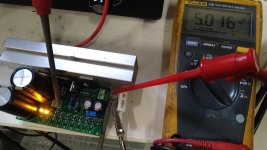
- Here is a schematic with typical reservoir caps values and some pictures. That soldering iron pulled 55W peak from the mains through the PSU to boot and idled at 12W. The scope pic displays Vin ripple on C4 vs Vout status captured at a point when the iron was still pulling hard to heat up started from room temperature cold state.
The Fluke reads C4's raw DC level in another picture. Started at 27V idle with worst loss of 4V during the soldering iron's boot cycle (trafo, diodes, rippleV). At 23V raw DC for 18V output to the iron, that trafo and reservoir caps passed the 2.5V Vin-Vout criterion by double margin. Other type & quality trafo or diodes could lose more or less steam of course. Higher value reservoir caps would achieve less ripple voltage but would also make the diodes work harder. Since the worst raw DC level sufficed, better not increase the caps value in this case.
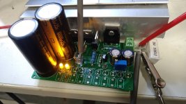
The example has 4xMUR860 & 2x4700uF/35V B41231 EPCOS/TDK. Also a 38mm tall Q2's sink. Which sufficed due to the irregular current pull of the micro controlled soldering iron. Can it do an RPi3? Yes I tested it with Wi-Fi and streaming vids on the Raspbian OS. Can it do a 12V Windows 10 Cherry Trail mini PC? Yes I tested it. Watched a whole movie stored in a mechanical 2.5 inch USB Hard Disk attached to it. The PC was at the same time charging an OnePlus X phone from a spare USB output so I pushed it further. I now used lower voltage and smaller size transformers than that R-Core. EI or toroidal of average quality. They and the sinks sufficed again because of the irregular current pull of computers with idling gap periods. 45C on the 38mm 35C on the 25mm ones for the diodes. Minimal RPi use shouldn't need diode sinks at all.
- In the final black & gold boards there are actual Q1 Q2 designations. In the first photo of the green prototype you may spot Q3 Q4 instead. They are just a relic from an earlier schematic with extra parts due to various discrete CCS tests until ending up using IC1. Forget about those Q3 Q4 prototype marks.
- I will be editing & enhancing post #1 in later installments.
- 25/6/2019 Build guide added (includes circuit description & BOM) - attachments rearranged
There's no stability issue with output wiring and load reactivity in the L-Adapter as there's no loop feedback outside its Sziklai transistors compound pair. About making such a pair with Mosfets I don't know of possible issues as I have never seen an example. One thing is due to Vgs > Vbe it would be less efficient.
Hello Salas,There's no stability issue with output wiring and load reactivity in the L-Adapter as there's no loop feedback outside its Sziklai transistors compound pair. About making such a pair with Mosfets I don't know of possible issues as I have never seen an example. One thing is due to Vgs > Vbe it would be less efficient.
Happy new year 🙂
I’m using L-adapter to power my RP4. It has a strange behavior, sometimes RPi crashes. Today I had a lite time to investigate the issue, and I connected my oscilloscope to the output, and started the RPi. I set the output voltage 5.2V. Normally the output voltage is precisely 5.2V, but sometimes the voltage started to drop until 4.3V. Sometimes it’s jumping back to 5.2V within a sec, but sometimes it is oscillating between 4.3 and 5.2V. Then stabilizing precisely 5.2V
I’m using 10V/5A toroidal transformer, and the C3 C4 capacitor is 10.000uF. Do you have any idea, what causing this issue?
Hi, happy new year to you and to all.
First confirm connectors aren't bit loose or wire gauge isn't relatively thin towards the RP4 dropping voltage due to resistance in power peaks. If it drops much at RP4's input vs at L-Adapter's output, then that's it. Second, see if the DC drop across D11 is going below 2.5V at those low Vout moments.
First confirm connectors aren't bit loose or wire gauge isn't relatively thin towards the RP4 dropping voltage due to resistance in power peaks. If it drops much at RP4's input vs at L-Adapter's output, then that's it. Second, see if the DC drop across D11 is going below 2.5V at those low Vout moments.
Give Salas a good photo to look for trouble.Hello Salas,
Happy new year 🙂
I’m using L-adapter to power my RP4. It has a strange behavior, sometimes RPi crashes. Today I had a lite time to investigate the issue, and I connected my oscilloscope to the output, and started the RPi. I set the output voltage 5.2V. Normally the output voltage is precisely 5.2V, but sometimes the voltage started to drop until 4.3V. Sometimes it’s jumping back to 5.2V within a sec, but sometimes it is oscillating between 4.3 and 5.2V. Then stabilizing precisely 5.2V
I’m using 10V/5A toroidal transformer, and the C3 C4 capacitor is 10.000uF. Do you have any idea, what causing this issue?
When I do that, he can usually spot the problem if the first tests don't provide the answer.
Rush
Hello,Hi, happy new year to you and to all.
First confirm connectors aren't bit loose or wire gauge isn't relatively thin towards the RP4 dropping voltage due to resistance in power peaks. If it drops much at RP4's input vs at L-Adapter's output, then that's it. Second, see if the DC drop across D11 is going below 2.5V at those low Vout moments.
The voltage drop is around 8.2-8.3V. 13.47V on one side, and around 5.2V on the other side. And not changing significantly when the stability issue are there
- Home
- Amplifiers
- Power Supplies
- L-Adapter