You want the heaters to come up slowly, for longevity of the heaters?using L-Adapter to drive tube heaters… is there a way to obtain a slow turn on? Something around 3 - 4 sec.?
Will you also slow the turn on of the high voltage to the plates to
avoid cathode stripping, or do I have that wrong?
yes, I will have double switch in the amp... one for L-adapter and one for SSHV2... normally I switch on only the heaters, slow turn on 5 - 10 sec. and wait about a minute before turning on all the other circuit, then will be the time required to charge capacitors to guarantee slow turn on also for high voltage... at least that is what I have now, hope I will be able to obtain the same functionality also with this new architecture
till now I've used a solid state relay to detect heaters voltage applied at tubes to enable the power supply to the other part of the circuit, in this way high voltage can't be applied in absence of heaters power
yes, the target is to reduce as much as possible the mechanical stress ... prevent cathode stripping comes as conseguence
Hi Salas, I’m new to digital sound and this forum, and have learned a lot from diyaudio and this thread in particular. Many thanks! I saw the photos of similar setups using dual power supplies, but would like to power my RPi 4 and Topping E50 from a single power supply. Is it practical to power both at 5V from a single 50VA 9V transformer/L Adapter? I assume the power requirements would be met, just wondering why the dual units were used and about noise to/from the RPi and DAC. Would additional filtering be necessary? Apologies if this question has been answered, I’ve searched the site and this (extensive!) thread and couldn’t find an answer.
Of course It's possible to power multiple same voltage spec devices from a single power source.
But it's a rarely seen practice in diy audio because builders usually strive for best isolation and care less about cost and size.
Unfortunately I don't remember about single PS vs dedicated PS RPI + DAC evaluations reported here so to enlighten you. If someone reading has done such a comparison please let us know more.
In any case you could start with a common L-Adapter PSU for your RPI + DAC and compare dedicated by also using the DAC's factory PS. Or with a second L-Adapter down the road if you will ever build yet another for some new application.
Hello again. The L-adapter build was straightforward, no issues! I’ve built the double PS/L-adapter using two 50VA toroidal transformers from Antek each with two 9V secondaries wired in parallel to the two L-adapters. The transformers are fed 120V through a Schurter filtered inlet, with its ground attached to the chassis. (The purple shield wires from the transformers are not connected to anything.) I am getting 5.0V output from the L-adapters, however I am also getting 45-50VAC between the chassis ground and the 9V secondaries, which I feel is not safe. Can you give me an ideas on how I should correct this?Of course It's possible to power multiple same voltage spec devices from a single power source.
But it's a rarely seen practice in diy audio because builders usually strive for best isolation and care less about cost and size.
Unfortunately I don't remember about single PS vs dedicated PS RPI + DAC evaluations reported here so to enlighten you. If someone reading has done such a comparison please let us know more.
In any case you could start with a common L-Adapter PSU for your RPI + DAC and compare dedicated by also using the DAC's factory PS. Or with a second L-Adapter down the road if you will ever build yet another for some new application.
Attachments
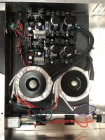
@jdkinase,Hello again. The L-adapter build was straightforward, no issues! I’ve built the double PS/L-adapter using two 50VA toroidal transformers from Antek each with two 9V secondaries wired in parallel to the two L-adapters. The transformers are fed 120V through a Schurter filtered inlet, with its ground attached to the chassis. (The purple shield wires from the transformers are not connected to anything.) I am getting 5.0V output from the L-adapters, however I am also getting 45-50VAC between the chassis ground and the 9V secondaries, which I feel is not safe. Can you give me an ideas on how I should correct this?
Looking at the picture I noticed that you have taken precautions by marking the polarity of the dc-out of the L Adapter using red paint for positive. I am attaching a picture of one of my boards and I show the polarity markings on the board outputs. The black wire is for ground(0V) and the red wire is for positive or 5V. Did you make changes to your board so that the polarity is reversed on the outputs? My note does not address your issue with the chassis ground and the 9V secondaries. Sorry.
Attachments
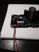
@ktham. Good eyes! Thanks! Yes, I did change that after taking the photo.@jdkinase,
Looking at the picture I noticed that you have taken precautions by marking the polarity of the dc-out of the L Adapter using red paint for positive. I am attaching a picture of one of my boards and I show the polarity markings on the board outputs. The black wire is for ground(0V) and the red wire is for positive or 5V. Did you make changes to your board so that the polarity is reversed on the outputs? My note does not address your issue with the chassis ground and the 9V secondaries. Sorry.
https://www.diyaudio.com/community/threads/what-with-toroids-earth.364148/@ktham. Good eyes! Thanks! Yes, I did change that after taking the photo.
Look at Posts 4 to 9 at the above link to answer the question on the purple shield wire. Connect mechanically and electrically both the transformer purple wires to the green wire from the IEC socket. Make sure that you have a solid mechanical bond between the fastener and the other side of the chassis and it should not be painted. A serrated washer on the painted side of the chassis will provide a solid and mechanical and electrical connection. You need metal to metal connection between the chassis, the fastener and wiring. Do the measurements again with a load on the L Adaptor DC outputs. Good luck.
But he addressed that.
Regarding the static shield wires they drain noise to chassis best when they are also kept short. Less length inductance allows more HF drainage. The secondaries are isolated from the chassis. Because connected to full bridge unipolar schemes. PSU ground is the output zero not the chassis/mains protective earth. Thus they legitimately float to some ghost potential vs the chassis. Until we reference the chassis to PSU zero directly with a wire or through a loop breaking circuit they won't be correlated. Like Yin Yang or bridge diodes safety ground lift. R//C bypassed. In case we get ground loop hum or something.
Regarding the static shield wires they drain noise to chassis best when they are also kept short. Less length inductance allows more HF drainage. The secondaries are isolated from the chassis. Because connected to full bridge unipolar schemes. PSU ground is the output zero not the chassis/mains protective earth. Thus they legitimately float to some ghost potential vs the chassis. Until we reference the chassis to PSU zero directly with a wire or through a loop breaking circuit they won't be correlated. Like Yin Yang or bridge diodes safety ground lift. R//C bypassed. In case we get ground loop hum or something.

How good is the voltage regulation on L-Adapter?
I'm looking to power a NUC with it, that has max input of 19vdc and 3.6A - if I set up L-adapter for 15-18vdc output can I be sure that 19vdc input will not be breached if mains voltage happens to be higher?
Also, my NUC contains aftermarket Connor Winfield OCXO DOCSC master clocks. I have the option to power these separately, but would it be ok to power them all off a single L-adapter?
It's a bit of an odd arrangement in this used NUC I've picked up... for some reason there's a relay (Kam Ling KG1P-F) which both the DC jack (for the NUC) and 3-pin jaeger connector (for the Master clocks) connects into - thus the NUC needs two separate power supplies, or at least two feeds from a single power supply...
Attachments

Hi, the L-Adapter follows an internal DC voltage reference. Mains voltage fluctuation does not govern it. Its LEDS play that reference role. In other words it can fall little below than where you originally set its DC output due to heavy transient loading (mainly because of output cables resistance) but it will not overshoot. Set the DC out when unloaded. Make sure you read the pdf guide from post #1. Has recommendations about voltage range, power, and what transformers to choose among other things like sinking.
You surely can branch out its DC output and L-Adapter will be OK with that.
You surely can branch out its DC output and L-Adapter will be OK with that.
What kind of case is this that you're using here; can post a link?It's a bit of an odd arrangement in this used NUC I've picked up... for some reason there's a relay (Kam Ling KG1P-F) which both the DC jack (for the NUC) and 3-pin jaeger connector (for the Master clocks) connects into - thus the NUC needs two separate power supplies, or at least two feeds from a single power supply...
Plato X7 - https://www.akasa.com.twWhat kind of case is this that you're using here; can post a link?
Brilliant - so that is what I shall do!Hi, the L-Adapter follows an internal DC voltage reference. Mains voltage fluctuation does not govern it. Its LEDS play that reference role. In other words it can fall little below than where you originally set its DC output due to heavy transient loading (mainly because of output cables resistance) but it will not overshoot. Set the DC out when unloaded. Make sure you read the pdf guide from post #1. Has recommendations about voltage range, power, and what transformers to choose among other things like sinking.
You surely can branch out its DC output and L-Adapter will be OK with that.
Thanks to Salas for a great product. I use the Ultrabib already with really good result. I have trouble understanding how to use the Lm334 regulator in this L-adapter. Is it as described in picture attached?


- Home
- Amplifiers
- Power Supplies
- L-Adapter