
Planning to eventually replace that with something thicker, shorter, with better quality copper?I use the same cable supplied with the SMPS.
Silicone jacketed power cables especially are very nice in use.
Yes salas you are right,with the UBIB i use this '13AWG'.Silicone jacketed power cables especially are very nice in use.
Hello,
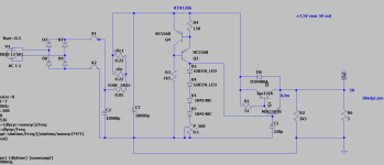
As I had no LM334 current source available, I thought I try something else as CCS for the LED/diode string.
Goal is to have 5V fixed supply.
Result: in a 5R load, the thing is oscillating >100mHz 40mVpp.
Below is circuit as build.
Any ideas to get rid of the oscillation?
Noise wise: any idea whether this would give better results than a LM334?
Attachments
Try a 100R resistor between D2 anode and + C1 first? Then higher R4? Then other type Q3 Q4? Then something slower than that Sanken main pass transistor?
Due to C1 filtering the Vref which is also unity gain (doesn't amplify its own noise) I don't expect you will see significant noise advantages on the rail with this.
Can bump into instability surprises and exaggerated thermal drifts when modifying the original. That's from experience because I tried few different discrete Vref schemes and various pass duet transistors types before settling to a specific L-Adapter configuration. Its superficially a very simple circuit but it was tricky to make it work just right. Board layout including.
Thanks for the feedback Salas, wil try Tomorrow.
I used the njw0302, mje15028 combo, but no Space modems for this.
I used the njw0302, mje15028 combo, but no Space modems for this.
Try a 100R resistor between D2 anode and + C1 first? Then higher R4? Then other type Q3 Q4? Then something slower than that Sanken main pass transistor?
Due to C1 filtering the Vref which is also unity gain (doesn't amplify its own noise) I don't expect you will see significant noise advantages on the rail with this.
Can bump into instability surprises and exaggerated thermal drifts when modifying the original. That's from experience because I tried few different discrete Vref schemes and various pass duet transistors types before settling to a specific L-Adapter configuration. Its superficially a very simple circuit but it was tricky to make it work just right. Board layout including.
Inserting an R (100R) between D2 and C1 ==> no impact on oscillation frequency and amplitude
Increasing R4 (reducing current through diode string) ==> no impact on oscillation frequency and amplitude
I will order some LM334 and follow your proven design!
100MHz+ is very high, thus also investigate if its some kind of interference intruding the test loop looking like an oscillation?
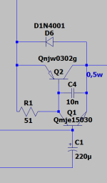
Update: as I had oscillation (post 1086), I put in a LM334 as per original design.
Result: 9.4mHz 200mVpp oscillation. (I doubt I measured oscillation correctly in post 1086)
What I did to stop it is: putting a 10n film cap between the emitter and collector of the MJE15028 (15030 in spice).
In spice, this has no negative impact to ripple.
Result: 9.4mHz 200mVpp oscillation. (I doubt I measured oscillation correctly in post 1086)
What I did to stop it is: putting a 10n film cap between the emitter and collector of the MJE15028 (15030 in spice).
In spice, this has no negative impact to ripple.
Attachments
A Miller cap. Alright. So the oscillation originated in the Sziklai CFP. Weird, we haven't had a precedent. Are you using trusted vendor transistors and the standard board design?
All components haven been purchased at Mouser or Reichelt. All active parts are from Mouser.
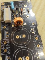
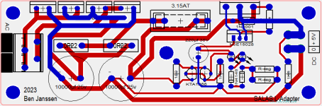
Below is a snip of the PCB used for the circuit in post 1086. Now to try the LM344; 150R, 1k5 and 2x KTA1266 ahve been removed to make place for the LM344.
Below is a snip of the PCB used for the circuit in post 1086. Now to try the LM344; 150R, 1k5 and 2x KTA1266 ahve been removed to make place for the LM344.
Attachments
The essence is to have it work as expected. Since you could compensate an anomaly all is well.
Newby question... Why is F1 placed between the 10000uf capacitors instead of right after the bridge?
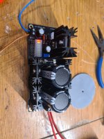
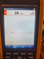
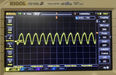
Finally iam joining the club . Would like to ask if this ripple values are acceptable ?
I Set scopemeter to ac coupling and measure ac peak to peak and ac voltage as you can see on picture . No sound test yet its late today . Tommorow it will power allo usbridge signature with upgraded rpi4 compute module .
I Set scopemeter to ac coupling and measure ac peak to peak and ac voltage as you can see on picture . No sound test yet its late today . Tommorow it will power allo usbridge signature with upgraded rpi4 compute module .
I use my L-Adapter with Allo USBridge and no regrates. You made right choice. 🙂
- Home
- Amplifiers
- Power Supplies
- L-Adapter