To clarify, the drive to the output gate resistors.
So, after lifting R11, what is the status of the amp? Is the green LED lit or red LED lit or flashing?
Is the power supply producing rails and what is the +/- rail Vdc,+/- regulated Vdc?
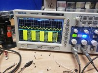
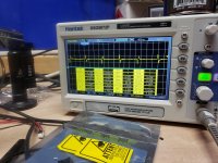
Do you have drive(squarewave) to the Output mosfets? Post screenshots for both banks on either side.
Check U14 Pin 3(triangle wave) and Pin 11(Squarewave) and post screenshots.
It's possible you will have to populate the output mosfets (one IRF640 and two IRF9640 on each side)in order to produce drive, due to the four 9640's to three 640's and feedback loop.
It's been a while since I worked on the model, and I've slept since then.😀 I know the back and forth can be a bit frustrating,but I believe this amp even despite it's complexities can be repaired. Please give me as much detail as you can,in a concise and organised manner.
Also one or more of the drivers Q113,135-A1361, Q104,126-C3503 may have failed. I'm not sure the inductor is bad, judging by the photos you sent, but it should be considered suspect.
So, after lifting R11, what is the status of the amp? Is the green LED lit or red LED lit or flashing?
Is the power supply producing rails and what is the +/- rail Vdc,+/- regulated Vdc?
Do you have drive(squarewave) to the Output mosfets? Post screenshots for both banks on either side.
Check U14 Pin 3(triangle wave) and Pin 11(Squarewave) and post screenshots.
It's possible you will have to populate the output mosfets (one IRF640 and two IRF9640 on each side)in order to produce drive, due to the four 9640's to three 640's and feedback loop.
It's been a while since I worked on the model, and I've slept since then.😀 I know the back and forth can be a bit frustrating,but I believe this amp even despite it's complexities can be repaired. Please give me as much detail as you can,in a concise and organised manner.
Also one or more of the drivers Q113,135-A1361, Q104,126-C3503 may have failed. I'm not sure the inductor is bad, judging by the photos you sent, but it should be considered suspect.
When you say "that resolved the issue" Do you mean the amp came out of protection? Was there ever a condition when you had drive on one side or the other?
Replace the Inductors, and remove all of the output mosfets. Lift R11-10k ohm. You will find it near Q10-3875GR. This should disable protection. If amp Powers up, check for drive/ squarewave at the gate resistors. Post screenshots for all banks.
Q113,135-A1361, Q104,126-C3503
Last edited:
Thank you for clarifying. I'm sure its frustrating trying to help a dummy. I'm just getting back into amplifier repair after a 6 month break so I'm a little rusty. I will post everything u asked for shortly. This definitely is the most complex amplifier I've ever attempted to fix. Without help from you and Perry it would be next to impossible to figure out. I dont know if the English language has the words for me to express my gratitude. It must feel very good to be able to help so many people every day.
After lifting R11 the amp powers up fine with the fets in drawing 1.3 amps at idle.
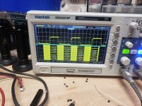
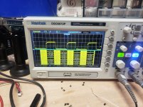
There is 63.4 volts on both positive Banks and -54.7 on both negative Banks however I did not see any Drive waves. I'm not sure I understand what "Regulated vdc" means
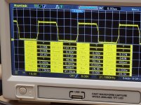
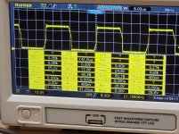
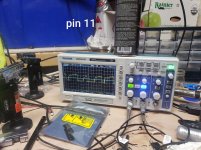
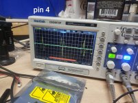
Pin 3 of U14 has -6.43 VDC but no triangle wave however pin 4 does have a triangle wave. Pin 11 does not have a square wave just 6.9 VDC.
Both c3503's and a1381's tested fine
There is 63.4 volts on both positive Banks and -54.7 on both negative Banks however I did not see any Drive waves. I'm not sure I understand what "Regulated vdc" means
Pin 3 of U14 has -6.43 VDC but no triangle wave however pin 4 does have a triangle wave. Pin 11 does not have a square wave just 6.9 VDC.
Both c3503's and a1381's tested fine
Last edited:
the measurement taken on the lm361 were done using the main ground. was I supposed to use the neg. speaker terminal?
Use the negative speaker terminal for all measurements. I think the difference between the the positive and negative rails is because you are using power ground.
You will see on the preamp/xover board the silkscreen for the +/- 12 regulated voltage.With black probe on the neg speaker terminal measure the regulated voltages.
Replace U11-TL072 and check for output drive/squarewave. at gate resistors. If you still don't have drive populate one mosfet per bank and check again.
No Dummy's here😉 just sometimes not on the same page. I'm usually not even in the same library!! 🙂
the regulated voltages are ok
I replaced U11 and have 1 fet per bank installed and still no drive wave
using the speaker ground the neg and pos rails are +/-59.5vdc all around
I replaced U11 and have 1 fet per bank installed and still no drive wave
using the speaker ground the neg and pos rails are +/-59.5vdc all around
Place a jumper(Maybe 22 gauge wire) between U14 Pin 4 and C270 (Speaker Ground side) and check to see if you have drive on Pin 11. If there is something in the feedback loop suppressing the drive barring any other problems this will prove that the comparator is working.
You might consider replacing the C3503's and A1381's drivers.
You might consider replacing the C3503's and A1381's drivers.
I pulled both c3503's and a1381's and tested them with a transistor tester and they all tested fine
yes. I still don't see any waves but when I play 100hz sinewave and adjust the vol the voltage fluctuates with it
I was wrong. I put fets in and it is functional with pin 4 jumped. it idles at 1.7a
Last edited:

- Home
- General Interest
- Car Audio
- kx1200.1 help