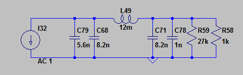
For anyone eager enough to attempt to modify their Kubelik here's what the modified 3rd order filter looks like. The new I/V resistor needs to be two resistors in parallel to match the 12mH inductor as E24 values don't come close enough. If anyone wants more details for the wiring how to bypass the opamps, just shout out. In the meantime I hope we'll get started on the PCB layout in the next day.
Attachments
AbraxIf anyone wants more details for the wiring how to bypass the opamps, just shout out.
You 've got to feed the fire.
Give all the details please
")
George
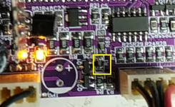
First we need to increase the current to the Vref as when using passive I/V the available current there needs to be higher than the maximum current the DACs can swing with both channels. R1 either needs replacing with 68R or you can solder a 150ohm over the top of the existing R1 (which is 120 ohm). As a result of this mod the yellow LED will glow brighter.
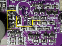
For the Left channel C24, R38, R41 and R42 are removed. R42 is replaced with 0R. R40 (2k) has 1k8 soldered on top of it.
Once U8 is removed, solder together pin2 and pin3. Solder a 0R or wire between pin5 and pin7 (shorting to pin6 doesn't matter).
Add a wire between R40 (inductor side) and U8 pin1.
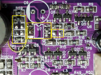
For the Right channel remove C25, R23, R60 and R61. R60 replaced with 0R. R62 has 1k8 soldered on top. With U7
removed short pin2 to pin3. Solder a 0R or wire between pin5 and pin7 (connecting to pin6 doesn't matter). Add a wire between R62
(inductor side) and U7 pin1.
For the filter mods - change the inductors to 12mH and solder extra NP0 caps on top of those already there. You'll need 2* 8.2nF to parallel with C12 and C18, 2 * 5.6nF to parallel with C14 and C20 and finally 2*680pF to parallel with C15 and C21.
All these mods will give you an opamp-free Kubelik that still needs 20V to operate. Supply voltage reduction mods I'll talk about another time.
For the Left channel C24, R38, R41 and R42 are removed. R42 is replaced with 0R. R40 (2k) has 1k8 soldered on top of it.
Once U8 is removed, solder together pin2 and pin3. Solder a 0R or wire between pin5 and pin7 (shorting to pin6 doesn't matter).
Add a wire between R40 (inductor side) and U8 pin1.
For the Right channel remove C25, R23, R60 and R61. R60 replaced with 0R. R62 has 1k8 soldered on top. With U7
removed short pin2 to pin3. Solder a 0R or wire between pin5 and pin7 (connecting to pin6 doesn't matter). Add a wire between R62
(inductor side) and U7 pin1.
For the filter mods - change the inductors to 12mH and solder extra NP0 caps on top of those already there. You'll need 2* 8.2nF to parallel with C12 and C18, 2 * 5.6nF to parallel with C14 and C20 and finally 2*680pF to parallel with C15 and C21.
All these mods will give you an opamp-free Kubelik that still needs 20V to operate. Supply voltage reduction mods I'll talk about another time.
Attachments
😁Abrax
You 've got to feed the fire.
Give all the details please
George
You got there first.

You only bought the one?For what the original Kubelik with op amp is, i am very satisfied with the sound.... i will wait for George to take the plunge and report his findings before i opt for the surgery
Thanks. Yes, it is happily playing music.
I have looked at those.
I don't know how much I would use it (is what I was thinking until I wouldn't mind dabbling with the other kubelik, have been looking at your mono amps, have picked up an unstarted WHAMMY SMD pcb hmmmmm)
I can't imagine getting through even 10% of what you use.
So, having a few of things would be quite handy for sure.
I didn't know what to get though.
I don't think I am likely to use loads, but could be any size, any value... so 10 of everything ?
Then I imagine having some caps would be handy.........
R36 and R62 are the I/V resistors on that schematic. On the PCB we're using a pair of resistors in parallel for I/V as I couldn't get the filter response I wanted with a fixed 12mH inductor with the usual E24 values.
@ClaudeG yes you're right about needing a volume control. There are a couple of ways to provide that that come to mind. First if your source is a PC or Android device there's normally digital volume available. For someone who shys away from digital volume (or uses a CD player without it) there's the option of using an AVC (autoformer volume control) directly between the output and the HPs. I have built a couple of those but so far haven't developed the control circuitry to allow remote control. It'll work fine with a manual rotary switch at present.
@ClaudeG yes you're right about needing a volume control. There are a couple of ways to provide that that come to mind. First if your source is a PC or Android device there's normally digital volume available. For someone who shys away from digital volume (or uses a CD player without it) there's the option of using an AVC (autoformer volume control) directly between the output and the HPs. I have built a couple of those but so far haven't developed the control circuitry to allow remote control. It'll work fine with a manual rotary switch at present.
- Home
- Vendor's Bazaar
- Kubelik NOS DAC kits