okay I must be missing some thing.
The drive tube is providing 25 v swing ?
How does this move the output tube into Class A/B or go into the "squishy zone"?
it might be off the charts but it looks like the curves are quite parallel in that zone.
The drive tube is providing 25 v swing ?
How does this move the output tube into Class A/B or go into the "squishy zone"?
it might be off the charts but it looks like the curves are quite parallel in that zone.
 These schematics may be copyrighted, posting copyrighted materials to the forum without permission of the copyright holder is a violation of forum rules. Please confirm that BlueGlow is OK with this. If not they will be removed. Please go read the rules.
gee kevin:
I am pretty sure those schematics are based on ones that were published on DIYAudio. Perhaps you should do the research before you issue warnings?? look up Mikael Abdellah Kt88se they seem fairly similar to me.
I am pretty sure those schematics are based on ones that were published on DIYAudio. Perhaps you should do the research before you issue warnings?? look up Mikael Abdellah Kt88se they seem fairly similar to me.
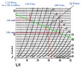
They aren't. The spacing between bias lines is always less to the right of the Q point than on the other side.it might be off the charts but it looks like the curves are quite parallel in that zone.
The result is even order distortion, 2H, 4H & so on. And also Zero H, that is the DC component. And plate current rises.
The harmonics & DC current are all part of the resulting Fourier Series of the resultant spectrum.
okay I must be missing some thing.
The drive tube is providing 25 v swing ?
How does this move the output tube into Class A/B or go into the "squishy zone"?
It's not the drive signal that determines the class of operation, it's the bias voltage of the output tube. If it's very negative (fixed bias) or very positive (cathode bias) then there isn't enough room for the (-) side of the signal swing to stay out of pushing the tube into cutoff. This amp will run without clipping the bottom for a limited volume position. That's OK class A. If this was a PP amp then it would be running in AB, and at higher volumes one tube would go into cutoff as it should while the other tube continues to amplify the (+) half of the signal as high as the swing will take it. Look how close the bias voltage is to the 0 current base line.
Everything on those schematics is prior art.
And used by many for a very long time. 🙂

Good to know. But the copyright does not prevent looking at it.The designs may be prior art, but the ARTWORK is copyright.
And very unlikely anyone would use it with the authors name attached.
Just like in the Hollywood Arts Community, if you're not in the news, You're not.
The author is getting some free press here. 😊 👍
Given he has posted this stuff on forums in the past, doesn't that make them public domain? I assume the stuff I have posted on forums is now public domain. If I could edit my earlier post, I'd remove it (and if the mods want to, I have no issue with them removing them) as people can easily find his schematic, or at least I thought people could until I saw someone posting different schematics with different tubes and voltages etc attributing that to him.The designs may be prior art, but the ARTWORK is copyright.
Last edited:
I Googled the Kegger Blueglow amp again & many hits resulted. And quite a few for other SE amps.
One from 2003 looks a lot like the present version. And looks like the original designer has his name on it.
And it has a Copyright mark as well. So rather than being censored here on DIY, here is the article link
for all to marvel at. 😀
http://diyaudioprojects.com/Schematics/Mikael-Abdellah-SE-KT88-Amplifier.htm
A Comparison. Yeh I know, this amp is ugly.
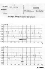
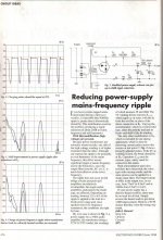
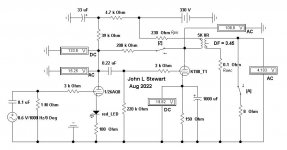
This project was originally published in the Glass Audio Projects book of April 2002 with 16 other vacuum tube designs. And uses the dissimilar 6LU8 twin triode. It is a follow on to the earlier Affordable SE 6EA7/6EM7 Amp published in The Glass Audio Magazine of July 2000. This version includes a circuit modification to reduce power frequency ripple in the high voltage supply. Power frequency interference is often at or close to speaker resonance. The PS LC filter is 12 db less effective at the power frequency than the full wave rectified ripple on the DC supply.
Equipment used in the development of this amplifier-
HP 200CD Oscillator
HP 302A Wave Analyzer
GW GAG-810 Oscillator
Rohde & Schwarz BOL 2 Trace 100 MHz Scope
RS 22-168A DMM
Sanwa AX 303-TR Analogue Multimeter
PicoScope ADC-216 Virtual Instrument
Electronic Workbench Software
I hardly need a website. Most of my stuff has been published.
And I’ve never copyrighted anything. Or tried to get a patent. Otherwise, only the lawyers win. Look at Armstrong’s problems with his invention of FM broadcast. And the Superhet circuit. Very little can be done to create a new version of a vacuum tube circuit. Without festooning it with semiconductors.
Attachments
-
 IMG_1620 Top.jpg448.7 KB · Views: 104
 -
 IMG_1619 Bottom.jpg326.6 KB · Views: 139
 -
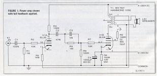 Figure One_Power Amp.jpg245 KB · Views: 143
 -
 Figure Two_ Power Supply.jpg286.3 KB · Views: 153
 -
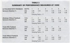 Table Two_ Summary of Performance at One KHz.jpg272.1 KB · Views: 119
 -
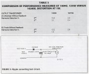 Table Three & Figure Three.jpg280.5 KB · Views: 113
 -
 GA28RIPPLEB 40C.jpg118.3 KB · Views: 101
 -
 AudioXpress Project Book 150 dpi.jpg776.8 KB · Views: 117
hello John:
Thanks for the circuit. I am just starting to study and comprehend it. Good for you that you chose to publish your circuits. I agree with that philosophy ideas should be shared so they can be enjoyed by many and perhaps improved upon to make an even better outcome. I also appreciate data to support the Diy person in the construction process.
I notice a discrepancy on table 3, did you compare to a 1627se or 1628se. Also could you explain the effect of damping factor?
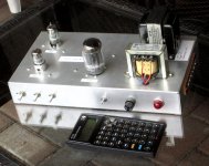
Your first photograph shows a pair of 6bq7 to the left of the chassis? Is that a pre amp section or a tone stack? I do not have the entire article to reference.
A very nice design with impressive performance figures good for you.
Thanks again
Thanks for the circuit. I am just starting to study and comprehend it. Good for you that you chose to publish your circuits. I agree with that philosophy ideas should be shared so they can be enjoyed by many and perhaps improved upon to make an even better outcome. I also appreciate data to support the Diy person in the construction process.
I notice a discrepancy on table 3, did you compare to a 1627se or 1628se. Also could you explain the effect of damping factor?
Your first photograph shows a pair of 6bq7 to the left of the chassis? Is that a pre amp section or a tone stack? I do not have the entire article to reference.
A very nice design with impressive performance figures good for you.
Thanks again
That is a good point, the OPT for that test was a Hammond 1627SE.I notice a discrepancy on table 3, did you compare to a 1627se or 1628se. Also could you explain the effect of damping factor?
When I started the original project for a 6EM7 SET, I was intending to go a least cost route.
This is an experimental amp as all my amps have been during the past 25 yrs.
There were some SE OPTs on the market but for a start I simply used a Hammond Universal, their 125E.
There were a couple in my stash. All of the tests would be done at 1000 Hz.
For the 6LU8 SET/SEUL version I simply changed the output tube socket & rewired for the 6LU8.
At the end of the tests on the 6LU8 UL version I did a comparison at a much lower frequency
using the H1627SE to get a look on performance improvement. Both versions sounded OK,
I did listen to the 6LU8 vers for a while as background tuned to local FM
If you like send me a private msg with your email., I've put both projects into PDFs.
And attached here is the original article covering power frequency ripple & reasons why it is worth doing.
I claim no Copyright or Copyleft on any of this. Just something I enjoy doing. 😀 👍
Attachments
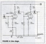
As I tested the earlier 6EM7 SE version of the amp I found that when the max NFB was applied the front end sensitivity was too low.Your first photograph shows a pair of 6bq7 to the left of the chassis? Is that a pre amp section or a tone stack? I do not have the entire article to reference.
There was plenty of space on the chassis, so two more sockets were installed. One 6BQ7 acts as a form of Line amp.
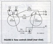
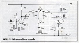
The other 6BQ7 is a complete Baxandall tone circuit, BASS & TREBLE controls.
The end result is something that can be driven by vacuum tube AM & FM Tuners from the 50s & 60s.
The line stage has a gain of 8 & looks like a source 1300R to the following load. 🙂 👍
Attachments
Back to the evaluation of the KT88SE circuit.
I must state upfront I am just learning circuit design, so my comments and question may be "all over the ice" so to speak. Please bear with me while I journey down this road to enlightenment. 🙂
I am still confused about your comments on the design. There is a segment of the series on the Blueglow website where he bench tests the constructed circuit. Here is the link for those interested:
(it is part 10 of the series.)
Mark gives it quite high praise and the data he presents does seem to look pretty good. The comments from 20to20 and John Stewart lead me to expect the measurements to not be too good. But.......
Perhaps the criticism was a bit hasty? or am I missing something again.
Thanks for the help
We made our points without being derogatory. Do some research on the difference between a class A operating point and class AB used for PP topologies. The drive signal for a properly biased class A amp swings the voltage from the bias voltage to near 0v on the grid at the peak of the signal, and then down going (-) the same value (-) + (-) to nearly double the (-) value of the bias voltage. It stays on the upper end of the load line or it fills the loadline all the way from 0v on the grid down to the cutoff voltage but no lower or else you get bottom clipping. That's how you get KT88 power from a KT88 SE amp. This design has the bias voltage over 20v too negative. It is a big tube toy doing the work of a 6BQ5 or 6L6. It's just for looks. It's an expensive tube and OPT being way underutilized.Back to the evaluation of the KT88SE circuit.
Perhaps the criticism was a bit hasty? or am I missing something again.
Thanks for the help
Last edited:
NC...We made our points without being derogatory.... It is a big tube toy doing the work of a 6BQ5 or 6L6. It's just for looks. It's an expensive tube and OPT being way underutilized.
And just curious, what do you think a "real" single tube KT88 SE amp should output in HiFi use with low distortion numbers? I'd also be interested to see either of you post a KT88SE schematic/design you have that isn't a just for show "toy".
I'd also be interested to see either of you post a KT88SE schematic/design you have that isn't a just for show "toy".
When and who first designated the CSXE25 OPT as a recommended tranny spec'ed @100ma? I see it's capable of 200mA per Edcor. Why is it carrying only 80mA in operation? I know the answer is plate dissipation @ 400+V.
So here is the KT88 in Class A, ~130mA Plate current. On a 330V PS. Plate dissipation is ~ 36 Watts.
Drop across the Cathode resistor is ~ 20 V & across the OPT Primary another 30V. The KT88 has 280V to work with.
Using different methods the 5K loadline is not suitable at all. Not surprising, the KT88 plate resistance is ~670R under these conditions.
For any common triode, theoretical max power occurs when Rl = 2 rp. But in practical amplifiers it is more like 2.5 rp.
But that brings with it quite a bit of distortion. So a professional designer might spec the OPT to be something like 3-4K.
That would result in more audio power than with the 5K OPT.
On the graphical method, power output is simply pk to pk voltage times pk to pk current divided by 8.
To get a ballpark figure for the OPT primary resistance I measured the H1627E I have here.
Attachments
- Home
- Amplifiers
- Tubes / Valves
- KT88SE - Power supply wiring, general query