So a professional designer might spec the OPT to be something like 3-4K.
That would result in more audio power than with the 5K OPT.
You beat me to that one. I was going to recommend the 2.5K version of that OPT as a better option to get the power out. The turns ratio would drop to @17 from 25. Then @ 300v on the plate @ 130mA you could (on paper) get nearly 500v swing on a 22v (peak ) drive signal. Biased @ -23ishV. I'm using the pentode charts and interpolating the screen voltage for the correct major curve divisions, based on the cathode/plate voltage.
Last edited:
Of course the recommended OT Z changes when you change the plate voltage... And yeah at 250V across the tube you want a lower bias voltage and a lower Z OT. But then you have to balance the distortion vs power lowering the Z of the OT creates, which also depends on the OT being used. And then how the amp sounds in use with the tube run at 250V and high current vs higher voltage and lower current. You can sim this till the cows come home, but what actually matters is bench testing the finished amp + listening to it.
Also they spec'd this larger 25W OT not because they need the ma rating, but from actually testing what the different OTs sound like listening to them. Have you listened to the differences in a KT88SE amp with a 15W vs a 25W Edcor OT? Kegger has, and he recommended the larger one based off listening tests as well as bench tests of the actual amp. Obviously the 15W version would work, and he stated that if your budget is limited, they will work OK.
And everything you both are saying is "on paper", totally ignoring the actual bench testing done on a completed amplifier that is clearly shown in his videos. A true scientist doesn't ignore empirical testing because it doesn't match up with their theories. Have fun playing with your slide rules.

Bunk! Just the comments of yet another self trained techie wannabe.And everything you both are saying is "on paper", totally ignoring the actual bench testing done on a completed amplifier that is clearly shown in his videos. A true scientist doesn't ignore empirical testing because it doesn't match up with their theories. Have fun playing with your slide rules.
All those Geezer Engineers & Physicists’ that managed to devise ways of creating a good vacuum so that we don’t have gassy tubes like Deforests used slip sticks. A lot. And many others who worked on cathode materials so that a room doesn’t have to light up when we use vacuum tubes. All used slide rules, log tables & many other aids common in their time. And no convenience such as an iPhone, so they could not alert others of what breakfast cereal they consumed this morning.
Perhaps they might invite you listen as an industrial grade system pulls a good vacuum.
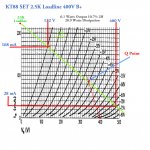
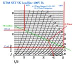
KT88 SET 400V B+ 2.5K Loadline
These simulation conditions manage ~7.3 Watts while plate dissipation is ~28.9 Watts. That is close to the theoretical for Class A, the power output is 25% of the plate input.
The graphical solution is close, easily within the same order of magnitude as it should be. Second harmonic is 10.7% & calculated by a simple formula often found in texts & data books. And attached here. 2H is proportional to output, so that at One Watt it would be ~1.5%. And could be further reduced by a NFB circuit. 😀 👍
Attachments
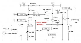
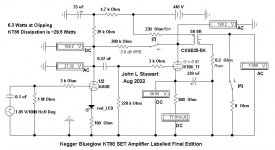
As requested, here are the results of the final version dated V6 2018 as posted on the Kegger Website.And FYI the actual distortion numbers of a sample of this amp, running the right tubes at the correct voltages, measured at 1% distortion is making 8W, at 5W is at 0.5% and at 10W it's still under 2%. For a SE amp those are really good numbers, the frequency response is flat and it has a lovely looking square wave. He explains all this in these two videos.
In SET mode the audio power available is ~5 Watts while the KT88 dissipates ~25 Watts. It will do a little better in SEUL.
And I'm certainly not trying to trash anyone's hobby, its been mine also for ~75 yrs. One gets to learn a lot over that period.
And still learning more now that I've finally retired from the hitech, high pressure business. But I'd do that all again too! 😀 😀👍
Attachments
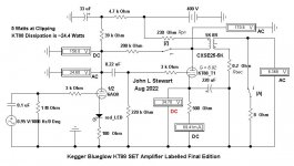
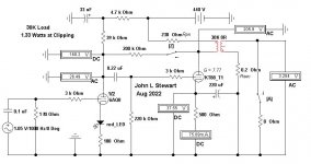
Here is the graphical solution for the Kegger Blueglow KT88 Amp Final Vers in triode mode.
The amp has about 2 db NFB, that will help the distortion figure a bit.
But neither solution comes close to the claimed numbers.
The B+ could be safely increased to about 440V with the 500R cathode resistor.
Alternatively, the 2H might be reduced by setting the cathode resistor to 400R.
These methods, without the help of digital devices have been used for about 80 yrs.
And found to be very good predictors of final circuit performance. 😀 👍
But if you like it, that is OK too.
Attachments
They aren't "claimed numbers", they are the actual bench tested numbers. You can watch the amplifier being tested with several different pieces of equipment. I bench tested mine after it was finished and got the same results.Here is the graphical solution for the Kegger Blueglow KT88 Amp Final Vers in triode mode.
The amp has about 2 db NFB, that will help the distortion figure a bit.
But neither solution comes close to the claimed numbers.
A scientist would be questioning why their theoretical, calculated and simulated results didn't match what happened with the actual built amplifier. But you are here questioning the honesty and integrity of other people, insinuating they made up the results, instead of realizing a simulation is only as good as the person doing it and the data they put into it. I know I'm going to believe the results I saw from actually bench testing a finished amp.
They aren't "claimed numbers", they are the actual bench tested numbers.
Even the originator of this design, with 400v and no plate-plate FB only claimed 5W. Boosting the B+ 10% isn't going to double the signal out power. There is another version/derivative of the original design done by Jean-Hiraga and can be easily searched on the same site as the others that is much closer to a better SE OP with a correct OPT and PT current rating, albeit still biased a bit too cold for some reason. Too much B+ and I couldn't find the primary I rating for his U-808 OPT. Maybe again another set of limitations...
Last edited:
Even Hiraga wasn't immune to the bigger is better fallacy as I see now 110uF of input cap ahead of a 10H choke. So that's where the extra B+ comes from.... geeesh. And who would use a single 5U4 for the stereo 300mA version...? And who among us wouldn't use a 50W cathode bias resistor if we had one???? It's published so it has to be right, vetted, tested and good...
Last edited:
No, ideal A is 50%, for choke/transformer loading.close to the theoretical for Class A, the power output is 25% of the plate input.
"25%" is an approximation for usual triodes in A1 which are FAR from ideal.
KT88 SET 440V B+ 30K Loadline
While that may be considered by some to be 'ideal', there is a fundamental problem. There is no usable output.
But common triodes are very tolerant to load resistance & most anything greater 3rp works well.
The upper limit is set by the designer, how much usable power to forego achieving lower distortion. 🙂
On this sim the PS could be increased & the plate current decreased while the Q point is pushed farther to the RHS.
But soon becomes SE Class AB.👎
Attachments
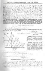
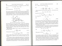
Here is a good reference from the distant past scanned from Samuel Seely's text book 'Electronic Tube Circuits'.
Its one of the McGraw-Hill Electronic & Electrical Engineering Series of text books from the 50s.
As I grinded my way thru the system this was one of the text I used & another of the same series by John D Ryder.
AC & DC Machines were covered in another text book authored by Michael Liwschitz Dr-Eng.
And yet another for Network Theory. And on & on. But all good. 👍 👍
Attachments

That passage from Seely is for the non-ideal case where rp is significant. And also somewhat constant.
Compare to a 6L6 (or KT88) pentode. rp takes two values, very high and very low. Any 19W 6L6 can make 8+ Watts in pent/tetrode. Load in 2500+r and swing down to the ~~250r saturation resistance.
Compare to a 6L6 (or KT88) pentode. rp takes two values, very high and very low. Any 19W 6L6 can make 8+ Watts in pent/tetrode. Load in 2500+r and swing down to the ~~250r saturation resistance.
- Home
- Amplifiers
- Tubes / Valves
- KT88SE - Power supply wiring, general query