Hi all,
Very quickly, I built a KT88SE (Kegger/Blueglow) and it has been working very well and I love it dearly!
I have been using a 5u4gb rectifier and would like to change this to a 5AR4/GZ34 for no other reason than to reduce the current draw on the Mains Tx. It is rated for 3amp 5v (Sowter) but it does get hot, barely achieving the 10 second rule.
My B+ measures 425v and with GZ34 (either JJ or Grove Tubes) I should get around the 450-460v mark or so.
So, my question, I have used standard Mains Cable (twin & earth) 300/500v (rightly or wrongly, probably wrongly) and although I have had no trouble or issues so far, I'm worried a little that the increase voltage may be little too much.
I've tried to understand Um of the cable but thought better to come here instead.
Thanks in advance
The amp is SE so Class A. The plate current does not change much provided the final stage is working properly.
A small resistance inserted between the GZ34 cathode & the first filter cap could be used to reduce the B+.
The resistance could be determined by trial. Try something like 100R for a start & adjust to the desired potential.
Overheating of the PT may be an indicator the first cap after the rectifier is too large. 🙂
Beyond cosmetics a quick look at the Blueglow website shews some very ordinary amplifiers.
Is your aamp running the KT88 in triode or pentode?
Last edited:
HiHi all,
Very quickly, I built a KT88SE (Kegger/Blueglow) and it has been working very well and I love it dearly!
I have been using a 5u4gb rectifier and would like to change this to a 5AR4/GZ34 for no other reason than to reduce the current draw on the Mains Tx. It is rated for 3amp 5v (Sowter) but it does get hot, barely achieving the 10 second rule.
My B+ measures 425v and with GZ34 (either JJ or Grove Tubes) I should get around the 450-460v mark or so.
So, my question, I have used standard Mains Cable (twin & earth) 300/500v (rightly or wrongly, probably wrongly) and although I have had no trouble or issues so far, I'm worried a little that the increase voltage may be little too much.
I've tried to understand Um of the cable but thought better to come here instead.
Thanks in advance
do you have a scheamtic?
As mentioned a trimmed resistors in series before the first cap helps for voltage and you can monitor the effective current deliverd also the impulsive current to charge the capacitors.
About heat maybe the trafo is not so well dimensioned
Walter
Thanks for the reply,The amp is SE so Class A. The plate current does not change much provided the final stage is working properly.
A small resistance inserted between the GZ34 cathode & the first filter cap could be used to reduce the B+.
The resistance could be determined by trial. Try something like 100R for a start & adjust to the desired potential.
Overheating of the PT may be an indicator the first cap after the rectifier is too large. 🙂
So, reducing the current of the rectifier from 3amp to 2amp won't reduce heat in the transformer?
I wouldn't say it is overheating, just running hot to touch for around 10-15 seconds. Blueglows states on his YouTube posting that his amp runs cool (5ar4) using a hammond Tx ( where these are said to run hot) and my Sowter is very overspec'd.
The first cap, poly, is 10uf, then into electro 200uf which is split 50uf + 50uf + 50uf +50uf. (Just as the circuit)
Resistance would be good and I do have 100ohm 50W metal encased resistors, so may give this a try although the increase in voltage may be welcome, although....
Could I just re-ask about the mains cable voltage rating please?, I have read that the Um of 300/500v is 600v, would that be the max line voltage?
Hi Walter,Hi
do you have a scheamtic?
As mentioned a trimmed resistors in series before the first cap helps for voltage and you can monitor the effective current deliverd also the impulsive current to charge the capacitors.
About heat maybe the trafo is not so well dimensioned
Walter
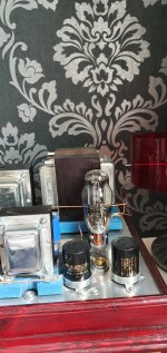
Schematic attached, hope Blueglow doesn't mind, plus a picture of transformer. As you see just behind a large 5u4gb it is a big Tx, 12kg worth.
Attachments


Reducing 1 A means 5 watt less, not so important.
If the temperature of the trafo is around 40° after some time and stay costant it is normal; take a note that a sensation with hand give you a non realistic value of the temperature
The cable, in my opinion are fine even I suggest always to use teflon cable for this purpose.
Regarding the voltage, try to check the Ibias of each KT88; probably they stay in the safe area again.
The tubes are generouse some time!
Put a amp schematic so we will see th details
If it is a self bias ciruit you can measure the voltage at the anode and the votage on the cathode, the difference is the effective voltage on tube.
Then the Ibias dividing the V on cathode by the value of R; in you calculate the Power dissipated from 88 and if it stay around the 70-80% of the max power dissipation permitted ( around 42 watt) the results is good.
Of course a check on the input stage is suggested but probably it will works fine.
Take measure with 5U4 and GZ34 so you can have a difference
One thing I can say for sure: do NOT use a JJ 5AR4. I can promise you it won't last long in this application. A TAD or a gold lion (or any NOS) will work fine. I think you are on the right path lowering the filament amp draw to reduce transformer temps. I also don't think you will have any issue with the higher B+ in the circuit and I don't expect the voltage gain to be as drastic as you suspect.Hi all,
Very quickly, I built a KT88SE (Kegger/Blueglow) and it has been working very well and I love it dearly!
I have been using a 5u4gb rectifier and would like to change this to a 5AR4/GZ34 for no other reason than to reduce the current draw on the Mains Tx. It is rated for 3amp 5v (Sowter) but it does get hot, barely achieving the 10 second rule.
My B+ measures 425v and with GZ34 (either JJ or Grove Tubes) I should get around the 450-460v mark or so.
Was this insult necessary and what did it add to the thread? Mark has done a lot for this community and see no reason for this.Beyond cosmetics a quick look at the Blueglow website shews some very ordinary amplifiers.
Reducing 1 A means 5 watt less, not so important.
If the temperature of the trafo is around 40° after some time and stay costant it is normal; take a note that a sensation with hand give you a non realistic value of the temperature
The cable, in my opinion are fine even I suggest always to use teflon cable for this purpose.
Regarding the voltage, try to check the Ibias of each KT88; probably they stay in the safe area again.
The tubes are generouse some time!
Put a amp schematic so we will see th details
If it is a self bias ciruit you can measure the voltage at the anode and the votage on the cathode, the difference is the effective voltage on tube.
Then the Ibias dividing the V on cathode by the value of R; in you calculate the Power dissipated from 88 and if it stay around the 70-80% of the max power dissipation permitted ( around 42 watt) the results is good.
Of course a check on the input stage is suggested but probably it will works fine.
Take measure with 5U4 and GZ34 so you can have a difference
Voltage on the anode is 425vReducing 1 A means 5 watt less, not so important.
If the temperature of the trafo is around 40° after some time and stay costant it is normal; take a note that a sensation with hand give you a non realistic value of the temperature
The cable, in my opinion are fine even I suggest always to use teflon cable for this purpose.
Regarding the voltage, try to check the Ibias of each KT88; probably they stay in the safe area again.
The tubes are generouse some time!
Put a amp schematic so we will see th details
If it is a self bias ciruit you can measure the voltage at the anode and the votage on the cathode, the difference is the effective voltage on tube.
Then the Ibias dividing the V on cathode by the value of R; in you calculate the Power dissipated from 88 and if it stay around the 70-80% of the max power dissipation permitted ( around 42 watt) the results is good.
Of course a check on the input stage is suggested but probably it will works fine.
Take measure with 5U4 and GZ34 so you can have a difference
Voltage on the cathode is 41v
I (think) that gives me 72ma but not sure. Divide by R to get power dissipation, again, not too sure if R is the cathode resistor (500r)
Which leads me to another important point. As a couple have said that the Blueglow site is rather ordinary, please consider not so educated DIY'ers like myself, who consider the Blueglow site to be an extremely valuable, educational resource he is excellent. This amp is simple but I did learn from him - super chap, really nice guy.
Agree with the JJ comment, can purchase TAD or Groove Tubes, NOS too pricey. Would like to give 5AR4/GZ34 a go, even if heat reduction is nominal
Thanks for comments all!
The cathode current is 82ma, ohms law of the voltage across the 500r resistor.Voltage on the anode is 425v
Voltage on the cathode is 41v
I (think) that gives me 72ma but not sure. Divide by R to get power dissipation, again, not too sure if R is the cathode resistor (500r)
Which leads me to another important point. As a couple have said that the Blueglow site is rather ordinary, please consider not so educated DIY'ers like myself, who consider the Blueglow site to be an extremely valuable, educational resource he is excellent. This amp is simple but I did learn from him - super chap, really nice guy.
Agree with the JJ comment, can purchase TAD or Groove Tubes, NOS too pricey. Would like to give 5AR4/GZ34 a go, even if heat reduction is nominal
Thanks for comments all!
I've personally used the TAD 5AR4 and it works well.
Like I said, I suspect you will only see 10-15V increase changing to a 5AR4, as the voltage drop across the rectifier varies with the load on it. Just keep an eye on the total dissipation, I find this site is helpful in determining that.
https://robrobinette.com/Tube_Bias_Calculator.htm
Just saying what people don't want to hear. The amps on Blue Glow are built for show, not GO. 😀Was this insult necessary and what did it add to the thread? Mark has done a lot for this community and see no reason for this.
Have you ever listened to one of them? And please link your website with videos and amp designs that are "built for GO." Like amps that have actually been built and reviewed, not just spice simulations.Just saying what people don't want to hear. The amps on Blue Glow are built for show, not GO. 😀
I think the OP is talking about the filament, not the HT/B+ unless I've got the wrong end of the stick. Without consulting datasheets and going off what the OP posted the 5U4G draws 15w for the filament - 3A x 5v, using a different rectifier with a lesser filament current draw, IE 2A would save the OP 5w if I'm right, not much of a saving.
An evaluation of the working conditions of the mains tfmr might be in order before making changes, for instance how hot is the tfmr? Is it noisy? Both are quick ways to figure out if the tfmr is running under duress. The general rules of thumb are AFAIK if a tfmr is too hot to leave a finger in place for more than a few seconds it's running too hard, same goes for noise; tfmr's running too hard are noisy, with the proviso that noise may be caused by other things like loose laminations etc.
Hope that helps, Andy.
Is 82mA a little hot?The cathode current is 82ma, ohms law of the voltage across the 500r resistor.
I've personally used the TAD 5AR4 and it works well.
Like I said, I suspect you will only see 10-15V increase changing to a 5AR4, as the voltage drop across the rectifier varies with the load on it. Just keep an eye on the total dissipation, I find this site is helpful in determining that.
https://robrobinette.com/Tube_Bias_Calculator.htm
I would have thought 60-65mA would be a little better, maybe this would cool things a little? Maybe increasing 500R to 750R.
To be honest though I don't think there is an issue with the transformer, due to the current ambient temp I have an oscillating fan on, intermittently blowing on the amp and I can keep my hand on the Tx indefinitely, mildly warm. But if course this may conceal core temp.
I don't have a web site. And at this age probably never will. But have built about 50 Toob amps over my lifetime.Have you ever listened to one of them? And please link your website with videos and amp designs that are "built for GO." Like amps that have actually been built and reviewed, not just spice simulations.
And a lot of other apparatus used in research. I learned my stuff during the so-called Golden Age of Toobz.
Then transitioned to Ge, Si & GaAs. Later many years in the hitech test equipment business.
Much of my work with Toobz, complete with photos & comprehensive test data have appeared here on DIY.
And several complete articles in Glass Audio & AudioXpress. And shorter articles in Electronics World.
All for anyone to trash if they wished!😀👍
It's sorta hot but IMHO SE amps sound better with the tubes run fairly hard. What you have now is ~85% which isn't a concern. Remember the "plate voltage" is the voltage across the tube i.e. the anode voltage to ground minus the cathode voltage to ground. Or simply measure from the anode to the cathode. So if the anode voltage increased to 440, the voltage across the tube would be only ~400V and if the cathode voltage stays at 41V across a 500R, it's still only at 88%. 410V across the tube and 45V on the cathode would be at 97% and warrant going to a 560 ohm cathode resistor. Going to a 750 would kill the amp's power and sound IMHO.Is 82mA a little hot?
I would have thought 60-65mA would be a little better, maybe this would cool things a little? Maybe increasing 500R to 750R.
To be honest though I don't think there is an issue with the transformer, due to the current ambient temp I have an oscillating fan on, intermittently blowing on the amp and I can keep my hand on the Tx indefinitely, mildly warm. But if course this may conceal core temp.
I'm still curious how you can proclaim that Mark's amps are all show and no GO if you have never built or listened to one of them. And given I've seen dozens of people who have built this one rave about how great it sounds (I'm one of them), it's confusing why you would feel the need to make these demeaning statements, when it has nothing to do with the OP.I don't have a web site.

In the rectifier. But assuming 95% efficiency in the power transformer, the heat in the power transformer is reduced 0.25 Watts, probably 1/250th of the total PT heat.save the OP 5w if I'm right, not much of a saving.
I've had four tube amps I could not hold the PTs on. All were working when I let them go.
- Home
- Amplifiers
- Tubes / Valves
- KT88SE - Power supply wiring, general query