Umm could be tempted at some stage to make some PCB mono-blocks out of it. However I am overloaded with amps at the moment.
Chris Hornbeck,
The CCS impedance needs to be compared to:
(1/Gm + ((1 + u) x Plate load Z)); Where the plate load Z, is the parallel of: plate resistor, RL and the next stage's grid resistor, Rg.
That simply means the cathode impedance is larger than 1/GM (sometimes much larger).
It works in the favor of the CCS being 'more effective' in that circuit.
I love your posts!
Earlier posts had 100 Ohms from each cathode that joined at the CCS.
That helps the quiescent plate voltages to be more equal (DC balance).
But it reduces the plate's AC balance.
Please let me know if I am incorrect.
Thanks!
That helps the quiescent plate voltages to be more equal (DC balance).
But it reduces the plate's AC balance.
Please let me know if I am incorrect.
Thanks!

Not sure if the plates AC balance improves or get worse. My gut feeling the AC balance is better with the resistors but the gain lower. I assume WRT the same output swing.
Last edited:
I didn't see a benefit from the 100R resistors in the LTP cathodes, not in the simulator, nor on the bench, so I took them out, frankly I'm not that interested in the DC balance.
I think that's OK as long as a bad DC balance does not cause clipping in the driver stage. What's your amp giving at full power 40W?
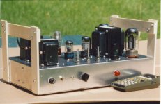
Curse all of the myriad of simulations, I built this one in 2001 as an experimental Circlotron.
And tried three different OPT systems.👍
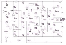
This project was originally published in the Volume 33, Issue 5 of AudioXpress magazine in May of 2002. It describes a high fidelity vacuum tube amplifier based the Circlotron from the 1950s. The circuit appears to be somewhat involved, but a closer look will reveal all. The primary object is to show what is possible with off the shelf parts & at reasonable cost.
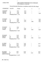
The D% results, with & without NFB speak for themselves. And without the multiple delays as simulations get in the way.
The AC balance Pot is a Mil Spec thing that is able to handle the 2nd Diff Amp plate current.🙂
And tried three different OPT systems.👍
This project was originally published in the Volume 33, Issue 5 of AudioXpress magazine in May of 2002. It describes a high fidelity vacuum tube amplifier based the Circlotron from the 1950s. The circuit appears to be somewhat involved, but a closer look will reveal all. The primary object is to show what is possible with off the shelf parts & at reasonable cost.
The D% results, with & without NFB speak for themselves. And without the multiple delays as simulations get in the way.
The AC balance Pot is a Mil Spec thing that is able to handle the 2nd Diff Amp plate current.🙂
Attachments

Baudouin0,
Thanks for the feedback! (Post # 245)
In my next amplifier that I use a CCS, I will try with, and without, the cathode resistors that go to the CCS (and with no resistors).
I may have to use a battery as a simple way to get a negative supply for the CCS. Usually my CCS are at ground at one end.
I barely have enough cathode bias voltage (and the cathode's negative swing with signal) to keep the CCS within its minimum burden voltage limit.
No simulation necessary, mother nature will give me the answers.
Once I do that test, I bet I take the battery out, and take the cathode resistors out, and go back to a grounded end of the CCS.
Last edited:
I think I saw this before - you were quite low on the CCS. You may do better with a current mirror which can go down to 1V or so. Think it had 12ay7 rather than 12ax7.
About 50 Watt before clipping at around 2% THD. It can do 60 with different settings but I’m not looking for quantity, my goal is quality.I think that's OK as long as a bad DC balance does not cause clipping in the driver stage. What's your amp giving at full power 40W?
OK for me the output power is a little low for the HT. Could be screen resistors 220R or could be the driver output hitting the HT rail or the OPT ratio. May not matter. I have 2 pairs of 6550A operation (UL) on 430V HT and this gives 120W rms so 60W per pair @ 430V. So 1 pair of KT88 at 520V maybe 70-80W. It may not matter to you but just check nothing is amiss. You maybe hitting saturation on the driver plates with 33k + 100k and the plate voltage. You may need to increase the CCS a little to lower the plate voltage.
Last edited:
No, everything is just fine, it is by design, it can do 60 Watt easily, with about 70 at 2% THD but the THD is much higher.
OK. I think your running the LTP cold. The result of this is I think is that the non linearity in the LTP stage and the non linearity approaching 0V on the grid of the KT88 start to cancel. This could of course be total rubbish. The danger is you may not drive the KT88 grid quite fully. The advantage is you won't get blocking.
I am indeed running the LTP cold, about 2.5mA per triode. This yields the best THD but not the highest output power, but as I mentioned I’m not interested in quantity, it is quality I’m after.
OK but I would aim to drive the KT88's fully. If the LPT is running out of current then you will get different results depending on the KT88 fitted, your bias and the HT voltage. In my books the design needs to be toleranced even it that means sacrificing some THD. Measuring the grid voltage on the scope of the KT88 will indicate if you have headroom or not.
- Home
- Amplifiers
- Tubes / Valves
- KT88 PP - Dotting the Is, crossing the Ts