Opinions please.
Hammond 1650N is a 60 watt 4300 ohm push pull output transformer with 4-8-16 ohm option.
Best I can measure my speakers are around 6 ohms impedance over most of the lower frequency range.
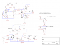
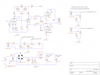
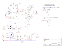
I'm doing a triode connected push-pull project (attached) Already had it running with KT88's many years back but never had the tools to measure anything.
Sooo...4 or 8 ohm tap? Ya I'll measure it when I get it built....
I'll post my progress on this project. So this post will be it for the project for all those interested.
I'm using a new power transformer for my KT120 version over what I used with the KT88 version (Hammond 290HX). PSU Designer II gives a B+ of ~460v. It has a 420mV rating so it was my choice for the project. My previous transformer only had a 250mA rating and sagged a wee bit as I recall.
Hammond 1650N is a 60 watt 4300 ohm push pull output transformer with 4-8-16 ohm option.
Best I can measure my speakers are around 6 ohms impedance over most of the lower frequency range.
I'm doing a triode connected push-pull project (attached) Already had it running with KT88's many years back but never had the tools to measure anything.
Sooo...4 or 8 ohm tap? Ya I'll measure it when I get it built....
I'll post my progress on this project. So this post will be it for the project for all those interested.
I'm using a new power transformer for my KT120 version over what I used with the KT88 version (Hammond 290HX). PSU Designer II gives a B+ of ~460v. It has a 420mV rating so it was my choice for the project. My previous transformer only had a 250mA rating and sagged a wee bit as I recall.
Attachments
I suggest you listen to bothe 4 and 8ohm, and you'll see the difference can be quite audible.
Just choose what you prefer
Just choose what you prefer
Have you built and tested the bias circuit feeding off the tap of the power transformer? Just today I was modeling a similar circuit and it does NOT work. I think it is because there is no direct ground reference for the bias circuit. The ground reference is created by the full wave bridge rectifier. If the transformer had a ground tapped into one of its windings it would work.
Have you built and tested the bias circuit feeding off the tap of the power transformer? Just today I was modeling a similar circuit and it does NOT work. I think it is because there is no direct ground reference for the bias circuit. The ground reference is created by the full wave bridge rectifier. If the transformer had a ground tapped into one of its windings it would work.
It's not obvious, but as long as the grid is not pulling current (and it shouldn't) the ground reference is through the FWB and the bleeder resistors. No current, no voltage drop across the two 330k resistors in parallel.
It should work.
Oops - I neglected the 30k voltage divider to set the bias... That could be a problem...
OK, this got me curious... The 290HX has a separate 100V winding that is likely being used for the bias. If so, all is good 😎
Last edited:
As long as he is using the separate 100v winding all is fine. If he is coming off the center tap of the secondary as the diagram suggests it won't work in my opinion.
And indeed, looking at the 290HX data sheet shows a 100v 50 ma winding which I suspect is being represented by "98v 50ma" tap in the schematic.
And indeed, looking at the 290HX data sheet shows a 100v 50 ma winding which I suspect is being represented by "98v 50ma" tap in the schematic.
No I have never used this Hammond model transformer before. However the bias winding is a separate winding as shown here:
http://www.hammondmfg.com/pdf/EDB290HX.pdf
I was just being lazy drawing it out....my bad.
http://www.hammondmfg.com/pdf/EDB290HX.pdf
I was just being lazy drawing it out....my bad.
Attachments
...I would never have noticed it except for having thought of trying to do that just today...
I would consider (for less ripple but probably not really necessary) a full wave bridge for the bias supply.
I would consider (for less ripple but probably not really necessary) a full wave bridge for the bias supply.
...I would never have noticed it except for having thought of trying to do that just today...
I would consider (for less ripple but probably not really necessary) a full wave bridge for the bias supply.
Ya I will use a full wave bridge in the bias supply...this ain't no stinkin' guitar amp! Thanks!
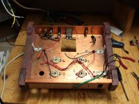
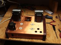
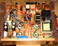
Attached are the now stripped down previous KT88 project chassis.
Attachments
First ... you have not designed a "triode-mode" amplifier. Sorry. You're using pentodes, as pentodes. [And I've got no problem with that. Good work!]
Second ... I'm glad you put in the separate B- supply - the first drawing wouldn't have worked as you expected, I think. [Then again, with an additional capacitor it would have worked ... as a voltage multiplier does! but that's a different story]
Third ... its not clear why you're using that poor little 12AX7 as the phase splitter ... when at full power operation the output tubes may well want current draw on their grids. I recommend at least considering socket-and-pin compatible higher current relatives, such as the 12BZ7, 12AU7, etc. The BZ is a particularly sweet tube, overall. You would need (and want) to drive it with more current though, choosing 11K cathode/anode resistors.
Fourth... since you're using a pentode ("cascode on the cheap") in the front end - always kind of ballsy in an audio forum site like this - why not keep on with the pentodes? They work great where the 12AX7 is in the circuit. Ultimately, the phase splitter is acting as a cathode follower - where the anode resistor is "along for the ride" (and thus accomplishes the phase splitting/inversion). So... why not use a tube whose IV characteristics are so much squarer and less dependent on cathode-to-plate voltage? Dunno... I would sub.
Your work looks good. Keep it up.
GoatGuy
The phase splitter is a 12AU7. Other schematics (By noted "designers") I have seen are using 47k resistors....I went with the 33k's which I will use as my starting point and see how it measures ...thanks for the tip.....it would appear I can go to 16k there easily with my 12au7. The 12BZ7 sounds like a tube I must try! Thanks!
I don't understand your first line...."You are using pentodes as pentodes." ? (Help!)
When this was first running as a KT88 indeed I was using the EF86 as a pentode and the KT88's ultra-linear with negative feedback....I spent a lot of time screwing around with the circuit and arrived at what you see. This was ~15 years ago when I first started playing with tubes. I didn't measure anything and just went with what sounded better to me. It will be fun to play around with the circuit now and see where I end up. As you can see I have a lot of options to try with my current tubes and transformers.
Thanks for the input.
[Then again, with an additional capacitor it would have worked ... as a voltage multiplier does! but that's a different story]
GoatGuy
Even with a cap in series with the diode I could not get it to work. The problem is not where it is tapped off, the problem is the ground return.
Hey... if you are building the rig as a "testbed for 15 years of ideas", then before you get too far in punching holes in sheet metal, consider putting in a few "substitution sockets"!
For instance, the front-end tube ... could have another socket that would accept the 12ax/au/bz7 family. The phase splitter, similarly could have 2 or 3 sockets ... wired up in advance for all the various kind of substitutes that fall within the 80:20 rule.
I'm sure someone here will yell, "but those unattached wires! Pickups of noise! bad Goat, bad!" ... actually its nowhere near as bad as many make out. There are a LOT of wires - leads to resistors, capacitors, between tubes, etc - inside every amplifier. Careful layout and using shielded wire both for grids and anode-side wiring saves the day.
I built something along this line, where every cathode-resistor was small-value pot and a series resistor (for safety, in case the wiper "wiped out" the pot's resistance); I also put a "driver pot" between the first and phase-splitting stages, so as to be able to raise front-end gain, but drop overall gain ... not to overdrive the outputs. [This is common now in "guitar amps"]. let's see ... I put switches in series with cathode capacitors (fast swap-in/out that way) ... and as I said, another exactly identical stage in front of your first stage.
Why exactly identical? ... think about it: if one stage, through the usual tubish nonlinearities, has a tendency to perk up the negative-signal excursions, but quash the positive-signal wiggles, then having another section that takes the inverted input and does the same thing in reverse ... gives better nonlinear symmetry overall. [And, if done carefully, eliminates the need for a phase splitter!]
Anyway, there are my "35 years of ideas"... well ... maybe 10% of 'em!
LOL
GoatGuy
deriving B- bias from centertap dual-use winding
I accept that. Voltage-multipliers are the height of "non-obvious how they work" devices. I could dig something up that DID work for me ... but unfortunately The Man now requires that I ... Get Back To Work.
Work work work.
GoatGuy
Even with a cap in series with the diode I could not get it to work. The problem is not where it is tapped off, the problem is the ground return.
I accept that. Voltage-multipliers are the height of "non-obvious how they work" devices. I could dig something up that DID work for me ... but unfortunately The Man now requires that I ... Get Back To Work.
Work work work.
GoatGuy
Hi
i have never used the KT120 as a triode, but i don't think the drive circuit would drive a KT88 as a triode, would even have trouble driving an EL34 as triode.
Phil
i have never used the KT120 as a triode, but i don't think the drive circuit would drive a KT88 as a triode, would even have trouble driving an EL34 as triode.
Phil
Hi
i have never used the KT120 as a triode, but i don't think the drive circuit would drive a KT88 as a triode, would even have trouble driving an EL34 as triode.
Phil
Phil are you talking about the drive circuit in my schematic? If you are why wouldn't it drive a KT88? It will have a little over 4 mA running through it.
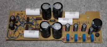
That looks sweet, I was wondering how you would solve the space issue😀 the PCB looks nice to.
Edit; on a cautionary note, glue everything on that board down whit hot glue, I've had heavy capacitors ripping the soldering joint on some of my projects.
Edit; on a cautionary note, glue everything on that board down whit hot glue, I've had heavy capacitors ripping the soldering joint on some of my projects.
Last edited:
GoatGuy said: Sorry. You're using pentodes, as pentodes. [And I've got no problem with that. Good work!]
No problem for me either. But as in the schematic, with the screen grids connected (via stoppers) to the plates, that is triode connection 🙂
No problem for me either. But as in the schematic, with the screen grids connected (via stoppers) to the plates, that is triode connection 🙂
I googled around for EF86-triode specs. Found the Klausmobile test for 6J32P wired as triode (Russian equivalent to EF86). Tube Tester Files - 6J33P (EF86)
It says the amplification factor is about 25 to 32. Let's say it's 25.
If you have a 1.5V rms input signal at the input, that's about a 2.1V peak input.
If the amp factor is 25, then the max output from the first (voltage amp) stage is about 50V peak.
That will be going through the cathodyne phase-splitter stage, which will have a gain of about 0.9, so that 50V gets chopped down to about 45V peak to the KT120-triode output stage.
Is that enough to drive KT120's to full power at the operating points you're running them? Or are you using a preamp with gain in front of this amp?
-RG
triode connected KT 120's
Melb ;I will be interested how your testing goes with this amp.
Never seen triode connected 6550's/KT120's driven by only a triode voltage amp and Phase splitter. You need a push pull driver as well.
Will have very slow dull sound.
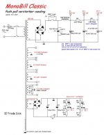
Take a look at this well designed KT88/6550 amp and it has an ultra linear output stage much easier to drive than triodes. Does your Out put transformer have ultra linear winding's? You may get better results using Ultra linear Or pentode. Dynaco used such a simple driver for Ultra linear KT88's as they are very easy to drive.
Phil
Melb ;I will be interested how your testing goes with this amp.
Never seen triode connected 6550's/KT120's driven by only a triode voltage amp and Phase splitter. You need a push pull driver as well.
Will have very slow dull sound.
Take a look at this well designed KT88/6550 amp and it has an ultra linear output stage much easier to drive than triodes. Does your Out put transformer have ultra linear winding's? You may get better results using Ultra linear Or pentode. Dynaco used such a simple driver for Ultra linear KT88's as they are very easy to drive.
Phil
Attachments

- Status
- Not open for further replies.
- Home
- Amplifiers
- Tubes / Valves
- KT120 "triode" and Hammond 1650N