Hello!
Just want to thank you ManoloMos for starting all this.
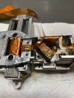
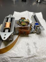
Yesterday I managed to successfully commission a KSS-168A Laserunit I had change the laser diode in.
Probably I had working examples in the past but All the time I had broken hardware around the laser unit.
I had 9 Blaupunkt CD41, CD42, CD43 and RDM43 and 2 Philips DC982 headunits to test the laser.
But all of them except for one had broken PCBs.
It seems like this units suffer from ICs breaking over time.
I suspect that Sonys CXD1125q and CXD2500AQ ICs break over time.
I will open a thread about this topic soon.
BTW: I never had my Photodiode signals intersect like you all have but it still worked out for me.
The Laser unit I have changed the Diode has some tracking issues.. I think I will need to work on the grating and diode alignment in the future.
Just want to thank you ManoloMos for starting all this.
Yesterday I managed to successfully commission a KSS-168A Laserunit I had change the laser diode in.
Probably I had working examples in the past but All the time I had broken hardware around the laser unit.
I had 9 Blaupunkt CD41, CD42, CD43 and RDM43 and 2 Philips DC982 headunits to test the laser.
But all of them except for one had broken PCBs.
It seems like this units suffer from ICs breaking over time.
I suspect that Sonys CXD1125q and CXD2500AQ ICs break over time.
I will open a thread about this topic soon.
BTW: I never had my Photodiode signals intersect like you all have but it still worked out for me.
The Laser unit I have changed the Diode has some tracking issues.. I think I will need to work on the grating and diode alignment in the future.
Hello!
Just want to thank you ManoloMos for starting all this.
Yesterday I managed to successfully commission a KSS-168A Laserunit I had change the laser diode in.
Probably I had working examples in the past but All the time I had broken hardware around the laser unit.
I had 9 Blaupunkt CD41, CD42, CD43 and RDM43 and 2 Philips DC982 headunits to test the laser.
But all of them except for one had broken PCBs.
It seems like this units suffer from ICs breaking over time.
I suspect that Sonys CXD1125q and CXD2500AQ ICs break over time.
I will open a thread about this topic soon.
BTW: I never had my Photodiode signals intersect like you all have but it still worked out for me.
The Laser unit I have changed the Diode has some tracking issues.. I think I will need to work on the grating and diode alignment in the future.
Don't touch the "grating". Clean it with air pressured, but don't manipulate it. I don't know KSS-168A, but it seems similar to KSS-150A, 151,152,190. And yes, perfect tracking is very critical, and sorry, Service Manual method is not the best way. I have some notes about it, and I have not it near, and I don't remember the "tricks" I think these "tricks" are at the begining of the thread.
And don't forget that performance of KSS-150A, 151,152,190 are not as perfect as KSS-272A and similars. But it forgivable.
[SIZE=4][B]ManoloMos[/B][/SIZE] I think this is amazing. I like the concept of being able to repair these players long into the future. However I have tried to read the discussion on the diodes themselves but was not able to keep track.
1. Are the required diodes in current production?2. Do we expect production to continue for a long time? (i.e. what is the perpetual industrial use that will ensure this.)
3. Are the diodes available from a reliable source?
4. Should we put together a "group buy" and try to procure 10k units? (maybe that qty. is too low to even dent a minimum order)
Apologies if this has been covered elsewhere.
Thank you!
5.6mm Laser Diodes are actually at production, but 9 mm Laser Diodes for our CD Players, no. LT022mc that is 9mm, is very scarce, and almost LT022mc in Ebay and Aliexpress are counterfeits or in bad state.[SIZE=4][B]ManoloMos[/B][/SIZE] I think this is amazing. I like the concept of being able to repair these players long into the future. However I have tried to read the discussion on the diodes themselves but was not able to keep track.
1. Are the required diodes in current production?
I don't know, but like in old electronic tubes, I think in the future you'll can get from New Old Stock(NOS)2. Do we expect production to continue for a long time? (i.e. what is the perpetual industrial use that will ensure this.)
Yes, but it depends of the supply source.3. Are the diodes available from a reliable source?
<div data-xf-p="1"><br class="Apple-interchange-newline">Time goes by, and old devices give pass to new devices. All in life pass. It is fun to do experiments with CDs and other stuff but, I am not in favour of it. </div>4. Should we put together a "group buy" and try to procure 10k units? (maybe that qty. is too low to even dent a minimum order)
Time goes by, and old devices give pass to new devices. All in life pass. It is fun to do experiments with CDs and other stuff but, I am not in favour of it.
Apologies if this has been covered elsewhere.
Thank you!
I appreciate the thoughtful reply, but I do not like the answer at all, lol. What if the "new devices" aren't any good? 🙂
1-As I wrote before, the company QSI produces laser diodes that could be a good base for repair.I appreciate the thoughtful reply, but I do not like the answer at all, lol. What if the "new devices" aren't any good? 🙂
Original designs differed in how anode and cathode of the laser diode and monitor diode are connected together.
QSI offers all variants. Adapter PCBs have to be designed, trivial.
http://qsilaser.com/download/Infra_Red/QL78F8SX_2019.pdf
2-There was 5.6mm to 9mm adapter rings available from digikey. Maybe I bought the last ones available,
but they could still be milled (or printed, but milling is better because oh heat dissipation)
on a CNC-machine or lathe. But I have some at home.
3-What was never done yet but should be trivial for an experienced engineer:
The Automatic Power Circuit has to be modified to work with a modern diode,
as those consume less power.
Bottom line:
Like almost every mechanical gear from the eighties, CD Players werde designed extremely robust.
The first generations inherited the mechanical built quality from Tape-Decks, Reel to Reel, Turntables
Remember the gearless drives from Sony, swing arms from Philips.
Glass-based lenses (but with the problem that the glue biding them together could rot)
Brushless CD-Motors were often used. With hifi-addicts listening to inferior vinyl
prices for used CDs have dropped extremely.
CD-Rot? No. I have 700 CDs, the first bought in 1984. Still playing, though heavily scratched.
So CDs will last!
Vintage-Audio-Laser was mentioned here several times. Since late November 2022,
there is a great article online describing the difficult alignment of the OPH-31 to 35,
also labeled as TAOHS laser.
These Olympus - made lasers can be found in every first
to third generation player besides Philips and Sony.
https://www.vintage-audio-laser.com/A-l-atelier-page-83#1
Bottom line:
Optical and mechanical alignment is even more crucial than with 3-Beamers,
the margins to work with are narrower.
In my experience, www.deepl.com is best suited to translate the text
from French to English.
@ManoloMos, I still have some questions... ;-)
In your drawing of the I/V amp using the AD826, there are jumpers on the non-inverting input of the opamp.
What are they for?
When you measure the receiver diodes of a KSS-272A, do you connect directly on the diodes?
And do you disconnect the diodes from the IC?
In your drawing of the I/V amp using the AD826, there are jumpers on the non-inverting input of the opamp.
What are they for?
When you measure the receiver diodes of a KSS-272A, do you connect directly on the diodes?
And do you disconnect the diodes from the IC?
The jumpers are for to carry to zero volts the output of the Operational Amplifier, so is more easy to visualise the signal in the oscilloscope. The input at the operational amplifier from the photodiodes A-F signals outputs usually to deliver some volts or decimals of volts, so, with the jumpers, add a oposite voltage to get the out to zero volts.
In the KSS-272, 270, 271, 273,274, 280, 281 etc... you can see there is some kind of integrated circuit that includes the photodiodes, this IC amplifies the A-F photodiodes and proceces for to hand over a RF signal completed.
If you look in the flat cable of the KSS-272a, there six connections that are loose, this connections lead to A-F photodiodes monitor points in the integrated circuit(Called Opic). These points are the A-F photodiodes points to monitore the A-F photodiodes. Don't solder to these points in the flat cable, because it breaks easily. Solder a tiny cable to the Opic connector. It is not easy, but is the best way.
Thanks ManoloMos... ;-)
Is there a way to measure the radial tracking error with this kind of setup?
I mean with a mirror and wobbling the lens... ;-)
I have a OPU here, laser and diode array in one housing, where I can adjust the tracking by rotating the laser in its mounting hole.
I would love to make a setup to measure this and set it up propperly in stead of trial on error.
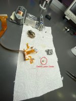
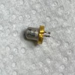
Hello everyone, I own a Sony CDP-337ESD CD player defective of KSS-190A lens. I disassembled the lens and determined that the laser diode is defective. Has anyone changed laser diode of KSS-190A before? If anyone has replace this diode before please tell me how can I find it. It's mark is 304 8BL. I couldn't find the producer of diode with this marking.
Attachments
maybe the attached datasheet helps a little despite the fact, that the mechanical outline isn't the same.
Check out also ths ebay offers:
https://www.ebay.de/itm/186111016338
https://www.ebay.pl/itm/186111016338
https://www.ebay.de/itm/175046576193
check out also this thread:
https://www.diyaudio.com/community/threads/fake-lt022mc-and-sony-diodes.357218/
Check out also ths ebay offers:
https://www.ebay.de/itm/186111016338
https://www.ebay.pl/itm/186111016338
https://www.ebay.de/itm/175046576193
check out also this thread:
https://www.diyaudio.com/community/threads/fake-lt022mc-and-sony-diodes.357218/
Attachments
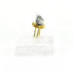

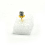
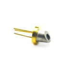

Hello. For KSS-190A, the laser diode necessary is a M Type, 780 nM and 5mW, 5,6mm. I've used always Rohm laser diodes different types and all worked satisfactory. I've had bad experiences with bad or counterfeit laser diodes.
I've opened some threads about replace laser diodes, but now I occupied in other activities.
In Ebay or other places I've seen some tecnician that do this kind of work.
Read the threads about this issue.
And, don't break your KSS-190a. Treat it with care.
I've opened some threads about replace laser diodes, but now I occupied in other activities.
In Ebay or other places I've seen some tecnician that do this kind of work.
Read the threads about this issue.
And, don't break your KSS-190a. Treat it with care.
tiefbassuebertr and ManoloMos
Thank you so much for your help. I am grateful to you.I will order and test it.
Hello. In Iccfl you can find some suitable laser diodes.
https://www.iccfl.com/product_info.php?cPath=252&products_id=31351&osCsid=fcggek87e3ij3uu0lrf9dtah63
There is another handicap with KSS-190a, 151a and similars, the handicap it that some adjusts like focus and tracking gain is very critical, service manual procedure adjustment is not the best way, and finally I've done the adjustment by the error-essay procedure. In JVC and Pioneer the adjust is perfect with its procedure, with Sony no. So, you can have a perfect KSS-190a but, however, you can have problems with some discs because the adjustment is not perfect. Best regards
maybe the attached datasheet helps a little despite the fact, that the mechanical outline isn't the same.
Check out also ths ebay offers:
https://www.ebay.de/itm/186111016338
https://www.ebay.pl/itm/186111016338
https://www.ebay.de/itm/175046576193
check out also this thread:
https://www.diyaudio.com/community/threads/fake-lt022mc-and-sony-diodes.357218/
Thank you for information I always believed the SM but will take a look error- essay procedure.Hello. In Iccfl you can find some suitable laser diodes.
https://www.iccfl.com/product_info.php?cPath=252&products_id=31351&osCsid=fcggek87e3ij3uu0lrf9dtah63
There is another handicap with KSS-190a, 151a and similars, the handicap it that some adjusts like focus and tracking gain is very critical, service manual procedure adjustment is not the best way, and finally I've done the adjustment by the error-essay procedure. In JVC and Pioneer the adjust is perfect with its procedure, with Sony no. So, you can have a perfect KSS-190a but, however, you can have problems with some discs because the adjustment is not perfect. Best regards
HI! I found some time to dedicate myself to these experiments.
As explained above, I only swapped the diode taken from another identical Pioneer optic frome same model PDR. I was trying to move only the diode, without touching the photodiodes.
Failing to position the source as expected, I positioned it as best I could, then fixed it and started moving the photodiodes. My tests have shown that it is much easier to move the photodiode array than the laser diode itself.
In fact, making an extreme comparison, a small movement of a light source will produce a large movement at the destination point. Since the laser travels a certain distance before reaching the photodiodes (including the mirror where it reflects and go back), moving the photodiodes is easier.
So I focused on A-B-C-D, leaving out E1 E2, F1 and F2.
After a few hours I reached the following result:
View attachment 1060494
It can therefore be seen that A and C (yellow, pink) are in phase and B and D (light blue, blue) are also in phase.
- light blue = B
- pink = C
- yellow = A
- blue = D
Note that the pairs are only shifted in position to aid visualization, but they all have the same zero volts.
So I fixed everything, removed all connections and reassembled the optic on the CD.
....Unfortunately the result was not what we expected:
The unit is able to focus, but it does not read the TOC and is unable to track. I rerun all the electrical and mechanical alignment steps in the service manual (including grating adjustment), but the result is as indicated.
Two questions arise at this point:
- Is it possible that ABCD are correctly aligned, while E1 / E2 and F1 / F2 are not? It does not seem possible to me as the sub photodiodes should be a consequence of the alignment of the four main ones.
- Furthermore, how much inaccuracy can we tolerate on the amplitude of ABCD? Considering that the algorithm (from service manual) for the tracking error is the following: {(B + C) - (A + D)} - {(E1-E2) - (F2-F1)}
it is clear that even a small difference in amplitude between the four pairs will lead to a tracking error!
Thank you.
Emanuele
Hello Emanuele,
I just now had a chance to read through this thread, and I am also glad and overwhelmed how much work was done on this topic. Looking at you results, you are very close! Is there any update, does the pickup read now.
Thanks in advance!
- Home
- Source & Line
- Digital Source
- KSS-190A with new laser diode. Applicable for the KSS-151A too.