I think I found the information I was searching for..
Link: https://www.diyaudio.com/community/...sd-rf-amp-inside-in-bu-1c.163529/post-2350463
Link: https://www.diyaudio.com/community/...sd-rf-amp-inside-in-bu-1c.163529/post-2350463
here is the best info about repair / service for CD player etc.
https://www.repairfaq.org/REPAIR/F_cdfaq.html
😎
https://www.repairfaq.org/REPAIR/F_cdfaq.html
😎
Hi! found some free time to work on my Pioneer laser diode alignement. OPAMP amplifiers board are complete, focus coil driver too.
I connect cables from flexible cable to my board for photodiode and laser diode and laser monitor to CD player.
First test is ok, with laser ON i can see signals from diode ad correct focus.
This is connection from service manual (notice there are 2 E and 2 F diode! I'm not sure why).

To be sure I understand, can you confirm that signals should be (according to the attached image from service manual):
Thank you!
Emanuele
I connect cables from flexible cable to my board for photodiode and laser diode and laser monitor to CD player.
First test is ok, with laser ON i can see signals from diode ad correct focus.
This is connection from service manual (notice there are 2 E and 2 F diode! I'm not sure why).
To be sure I understand, can you confirm that signals should be (according to the attached image from service manual):
- Signal A,B,C,D should be equal PPV level
- A should be in phase with C
- B should be in phase with D
- A and C should be 180° phase shifted with B and D
Thank you!
Emanuele
Hi.Which laser pickup is it? Can link any Pioneer service downloadable for to see this schema?Hi! found some free time to work on my Pioneer laser diode alignement. OPAMP amplifiers board are complete, focus coil driver too.
I connect cables from flexible cable to my board for photodiode and laser diode and laser monitor to CD player.
First test is ok, with laser ON i can see signals from diode ad correct focus.
This is connection from service manual (notice there are 2 E and 2 F diode! I'm not sure why).
View attachment 1055132
To be sure I understand, can you confirm that signals should be (according to the attached image from service manual):
- Signal A,B,C,D should be equal PPV level
- A should be in phase with C
- B should be in phase with D
- A and C should be 180° phase shifted with B and D
Thank you!
Emanuele
I haven't replaced any laser diode in a Pioneer pickup. The photodiode array is in a lateral, it looks a bit dificult to operate for to adjust. It's a challenge.
Hi @ManoloMos, this is a pickup from Pioneer PDR-99 or PDR-05, a Player/Recorder.
I'm not sure i can post a link, but it is available from here link
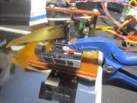
I had 2 units, one with corrupted optical blocks/grating but laser OK, and one with perfect optical but weak laser. So i swap laser diodes only. As you can see in the picture, it's easy to remove diode block because it has 2 screw only. The challenge is now to reallign diode itself!

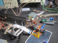
Here you can see the photodiode block, that i didn't touch, because i can move diode to reallign:

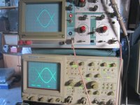
Yesterday i spent a lot of hours, but it's seems that i can get strange signal phases...
you can see below in the upper part C and D, below are A and B. THIS IS NOT CORRECT for what i understood, because i should have A and C 180° phase shifted, and NOT A and B. For what i seen, i was NOT able to get correct diode couple. I can only have 2 situations: Or all signal are in phase, or CD and AB are shifted like in the screen below. I really don't understand why.

What do you think?
Thank you,
Emanuele
I'm not sure i can post a link, but it is available from here link
I had 2 units, one with corrupted optical blocks/grating but laser OK, and one with perfect optical but weak laser. So i swap laser diodes only. As you can see in the picture, it's easy to remove diode block because it has 2 screw only. The challenge is now to reallign diode itself!
Here you can see the photodiode block, that i didn't touch, because i can move diode to reallign:
Yesterday i spent a lot of hours, but it's seems that i can get strange signal phases...
you can see below in the upper part C and D, below are A and B. THIS IS NOT CORRECT for what i understood, because i should have A and C 180° phase shifted, and NOT A and B. For what i seen, i was NOT able to get correct diode couple. I can only have 2 situations: Or all signal are in phase, or CD and AB are shifted like in the screen below. I really don't understand why.
What do you think?
Thank you,
Emanuele
Last edited:
Sorry i can't edit anymore my previous message. Regarding the last part i need to correct what i wrote: I think i should have for correct alignment:
If the above is correct, i will try again... for now, it seems that i can only have vertical (DC and AB) or horizontal (AD anc CB)) phase pair, but not X (AC and BD).
Thanks
- A should be in phase with C
- B should be in phase with D
- A and C should be 180° phase shifted with B and D
If the above is correct, i will try again... for now, it seems that i can only have vertical (DC and AB) or horizontal (AD anc CB)) phase pair, but not X (AC and BD).
Thanks
Hi! About Pioneer CDR of emanue member, this laser pickup have some challenges, both laser emitter as the photodiode array has adjustments, this issue adds a bit complex, because, which item do you adjust first? I'd replace first the laser diode and then I'd try to adjust the best wave signals, and then if it is necesary, I'd adjust the photodiode array.
Another problem, this is a CD recorder, which laser diode do you use for a replacement? Of course that it does not use a 5mw laser diode, but, which? 20mw? 100mw? I don't know. I'v never have expereminted with this kind of CD's.
The good point is that thanks to the screws, the adjustment looks more easy.
About the two E and F signals, in the manual is explained, I don't get the explanation in its totally, but it looks to be relationed to the recorder side. It's in the page 84.
The waves are almost right, but are not correct. Yes, I know that is very difficult reach to here, and can be discouraging to say that the signals are not right. With this signals, the CD should be able to read the TOC and read CD, but focus should not work properly, when you try to find a the best point, maybe it happens the following phonemena, and is that there are two focus points, first point where you reach a clean signal but low amplitude RF signal, and then another point where is a big RF signal but noisiest.
Don't worry about the E and F signals, A-B-C-D are the main signals, and must keep simetry between them, this is the key word: SYMETRY.
When you unfocus the lens, A-C and B-D must be similars. Symetry is not only when the focus is right, symetry must be respeted even with the unfocus.
This is a good example video.
Best regards
HI! I found some time to dedicate myself to these experiments.
As explained above, I only swapped the diode taken from another identical Pioneer optic frome same model PDR. I was trying to move only the diode, without touching the photodiodes.
Failing to position the source as expected, I positioned it as best I could, then fixed it and started moving the photodiodes. My tests have shown that it is much easier to move the photodiode array than the laser diode itself.
In fact, making an extreme comparison, a small movement of a light source will produce a large movement at the destination point. Since the laser travels a certain distance before reaching the photodiodes (including the mirror where it reflects and go back), moving the photodiodes is easier.
So I focused on A-B-C-D, leaving out E1 E2, F1 and F2.
After a few hours I reached the following result:

Note that the pairs are only shifted in position to aid visualization, but they all have the same zero volts.
So I fixed everything, removed all connections and reassembled the optic on the CD.
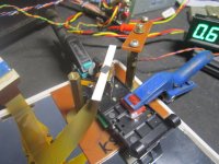
....Unfortunately the result was not what we expected:
The unit is able to focus, but it does not read the TOC and is unable to track. I rerun all the electrical and mechanical alignment steps in the service manual (including grating adjustment), but the result is as indicated.
Two questions arise at this point:
Thank you.
Emanuele
As explained above, I only swapped the diode taken from another identical Pioneer optic frome same model PDR. I was trying to move only the diode, without touching the photodiodes.
Failing to position the source as expected, I positioned it as best I could, then fixed it and started moving the photodiodes. My tests have shown that it is much easier to move the photodiode array than the laser diode itself.
In fact, making an extreme comparison, a small movement of a light source will produce a large movement at the destination point. Since the laser travels a certain distance before reaching the photodiodes (including the mirror where it reflects and go back), moving the photodiodes is easier.
So I focused on A-B-C-D, leaving out E1 E2, F1 and F2.
After a few hours I reached the following result:
- light blue = B
- pink = C
- yellow = A
- blue = D
Note that the pairs are only shifted in position to aid visualization, but they all have the same zero volts.
So I fixed everything, removed all connections and reassembled the optic on the CD.
....Unfortunately the result was not what we expected:
The unit is able to focus, but it does not read the TOC and is unable to track. I rerun all the electrical and mechanical alignment steps in the service manual (including grating adjustment), but the result is as indicated.
Two questions arise at this point:
- Is it possible that ABCD are correctly aligned, while E1 / E2 and F1 / F2 are not? It does not seem possible to me as the sub photodiodes should be a consequence of the alignment of the four main ones.
- Furthermore, how much inaccuracy can we tolerate on the amplitude of ABCD? Considering that the algorithm (from service manual) for the tracking error is the following: {(B + C) - (A + D)} - {(E1-E2) - (F2-F1)}
it is clear that even a small difference in amplitude between the four pairs will lead to a tracking error!
Thank you.
Emanuele
This signal is perfect. The cd should work perfectly with this laser pickup. This signal you show is almost impossible to improve, is almost perfect. I don't know what is happening, but I'm almost sure that the laser pickup is not the problem.
Hello everyone,
This is my first message on this forum. First of all, I would like to say thank you to everyone for sharing their knowledge.
I have a Sony D-15 Discman which has a KSS-165A optical pickup block. Unfortunately, with a deteriorated laser diode. 🙁
I was doing some online research about how to change the laser diode to bring this unit back to life but couldn't find any information to be specific to this optical pickup block.
Is there anyone who had some experience on this block before? If anyone, I have two questions:
- Which laser diode is compatible with KSS-165A?
- Is it necessary to re-align the photodiode array after replacing the laser diode?
I've never have seen this laser pickup. Looking in images on internet, it seems like a KSS-151a but flat, with the photodiode array in its lateral. The method, like you said, is to replace the laser diode and then, move the photodiode array to its correct position. But, as you can see, the disposition of the photodiode array at the side, make it adjustment more dificult.
But, I don't think the problem is the laser diode because, I don't think this discman have been used enough for to burn out the laser diode. Discman are not easy to manipulate.
I think another problem can be laser power potentiometer, that can be aged and modidy its value, and low the power emitted by the laser diode.
Another problem can be the electrolitic capacitors. I say "can be", because it is not for sure. I'm not in favour of replace electrolitic capacitors as a fixed rule. I replace if it are bad.
There can be another method to repair the KSS-165A, a crazy method, and is transplanting the optical, the metal piece which contains the laser diode, lens, and photodiode array from a KSS-151a or similalr which I know it works. Then, we have to adjust moving lens position. Crazy method as I said.
Dear Friends,
I am so happy to read this thread!
I had this idea 12 years ago but completely lacked the technical knowledge.
https://www.diyaudio.com/community/...kups-why-not-replacing-the-diode-only.158257/
Around 2018 I gave a working CDP-102 player, one BU-1 and ten LT022 diodes
(First generation diodes) to a DIYAudio-member to figure a diode swap.
He completely let me down on this and never sent me the items back until today.
(Interestingly he also never contributed to this thread.)
I also was very much consumed with documentary filmmaking the last 3 years, a 25/7 job:
https://fishermansframe.gumroad.com/l/abtyf
And the next documentary is already ahead - besides regular work-
so I do not know for the near future whether I will find the time to
built my own rig and start exploring the diode replacement.
So it is just great to read this and how far the project has progressed!
But there is one thing I do not understand:
Does the photodiode array always has to be aligned?
Because in a Sony BU-1, the first linear transport, the diode could be moved.
It is not glued in the cabinet of the laser assembly but fixed with a spring and
whashers that allow alignment and tilting in horizontal position.
Same with KSS123A. But it could be that this design was an exception.
This was not covered here yet:
I also looked into single beam Philips CDM-1 swing arms.
There, the diode (Also a Sharp LT-022MC) is pressed into an aluminium tube.
The photodiode array is glued to the mech, with 2k epoxy.
So if they really did it by aligning the array, it was time consuming.
Very interesting:
In the first gen. CD-100, the tube with the laser diode could be replaced!
https://elektrotanya.com/philips_cd100_cd_player_1983_sm.pdf/download.html
This was the times shortly before globalisation - the service manual is in german, look for page 8
Best,
Salar
I've replaced the laser diode in two KSS-151a. In one of them, I've replaced the flat cable, that is available in Ebay and Aliexpress. Works good. In one of them I had to replaced the moving lens, because it was broken. It cost a bit to get the best position. There is nothing new about the method for to replace the laser diode and adjust the photodiode array position. In these KSS-151a, I had to adjust azimuth screws too.
Attachments
Last edited:
Hi! No, the question is very important. You need DC current for to focus, it depends of the distance of the mirror, the own optics, etc... With DC current you adjust the focus, and with low frecuency, you have to produce a focus-unfocus movement. In this pic, you can see that what I mean.
This draw is not from a CD player laser pickup, but is useful for to show the idea.
View attachment 1047260
When you replace a diode laser, the problem is to adjust the position of the photodetector diode array, this is the main job we must search. For this, we use the astismatic propiery of the laser optic, with this propierty, you can see that if we moves the lens a bit forward(positive V in the graphic), the spot of the laser is converted in a elipse, that only iluminates c and a diodes. If we moves the lens backward(center, 0 v in the graphic), the elipses goes to the center, so is a perfect spot, same light in a-b-c and d diodes. If we give more negative, the spot light is converted in another elipse, that only iluminates b and d diodes.
View attachment 1047266
Comparing A-C and B-D is how Focus Servo works. E and F photodiodes are useful at the beginning, because when you start to adjust, are the first signals to appear.
When you mount the oscilloscopes, amplifier, and all the stuf, the right sinal must be something like that:
https://www.diyaudio.com/community/attachments/img_20211013_185031-jpg.1001283/
ManoloMos, thank you so much for sharing your experience with us.
There is one thing I don't understand though... ;-)
When you start to find the output signal, you use a low frequency signal which makes the optical lens go up and down and a very small dc voltage to give the focus coil a bias or preset.
I think I understand the priciple about the focus.
But how do you exactly know your optics are in focus when you start measuring?
What I mean is this: when for instance there is more light on diodes A and C (or diode B and D), this could be the case when the focus is not correct OR the diode array is not in the correct possition.
I mean, first we have to be sure the focus is correct and then we start moving the diode array in a way all signals are the same voltage level.
Or am I totally wrong here?... ;-)
Yes, you have understand correctly.
"But how do you exactly know your optics are in focus when you start measuring?"
I don't have any strict method. When you start find the position, E-F diodes signals are the firsts to appear. Then, when appears A-B-C-D signals, though this signals are not perfect, I put a mark with a pen, to put a mark helps for to find the place when you start from zero.
Well, then happens that, when you adjust the signals perfectly, if you move the mirror position, the signals appears dissadjusted. This is because there is a little margin of adjust. This margin of error is corrected with the screws of azimuth. Azimuth screws must adjust when you place the laser pickup playing.
Best regards

"When you start find the position, E-F diodes signals are the firsts to appear. Then, when appears A-B-C-D signals, though this signals are not perfect, I put a mark with a pen, to put a mark helps for to find the place when you start from zero."
Could you please explain a bit more ManoloMos?
"Well, then happens that, when you adjust the signals perfectly, if you move the mirror position, the signals appears dissadjusted. This is because there is a little margin of adjust. This margin of error is corrected with the screws of azimuth. Azimuth screws must adjust when you place the laser pickup playing."
You move the mirror?
I would like to be a sure as possible that the lof frequency signal runs around the zero-point = perfect focus.
I'm not sure what the consequences are when adjusting the array when the focus is not correct from the start.
The more I think about this, the less I seem to understand... ;-)
When you mount the laser pickup in the "gig", in the device for the adjustment, you mount all, you check if the laser power is transmitting, and then you try to find the signals, moving the lens throught the voltage adjustment with 23hz moving the lens too. Well, at the begining you don't find nothing, but when you move the diode array the first signals appear in the E-F diodes. This signals helps you to a do a gross adjustment. Then, is more easy to find the A-B-C-D signals. If you try to find A-B-C-D signals from zero, is not impossible, but is more difficult. Practice and experience will clear this issues.
The mirror is fixed, the mirror must be the more fixed and pararell to the laser pickup.
But it happens that when you have adjusted the laser pickup perfectly, you glued the photodiode array, you move the mirror, and you see that the signals are different, but don't worry. Then, when you mount the laser pickup in the CD player, you have to adjust the azimith. Why? Because the angle of the CD to the laser pickup is not exactly the same that when you adjusted the laser pickup with the mirror. In other words, there is a tiny adjustment difference betwen running with the mirror and playing with a real CD. Don't worry, this is adjusted with the azimuth screws in the lasere pickup.
If you are practicing with this, mount all the devices, the "gig", and try to see the wave signals.
Thanks ManoloMos...
I was just wondering, I have this Marantz CD player overhere and it is working just fine.
I tried to make some sort of signal visible on my scope and measured on the outputs of the TDA1302T.
I couldn't make any sence of what I saw on the scope, hardly any signal visible... ;-)
I also tried measuring after the RC combination, so directly on the inputs of the servo controller.
Same story, couldn't make anything sensible out it...
Very, very weak signal not recognizable as diode output signals.
Can it be done the way I tried? I mean, measuring while the cd is playing?
The optics are in focus.
I used no extra amplifier.
I see these kind of OPU's more, I mean an OPU already with some sort of aplifier like the TDA1302T as one unit.
Unbelievable that the servo controller can work with these level of signals...
For me it would be great if I could make a setup to check this kind of OPU at the outputs of the amp (TDA1302T)
.
ManoloMos, please ignore my last post... ;-)
When I think about it now, it's a dumb question...
The answer is hidden in my text already: the cd playing and optic in focus.
This means the signals from the amplifier are very small just to correct tracking and focus.
The best chance of seeing something on the scope is at the very startup of the cd-player.
I will use your technique with the low frequency to try and find some output from the amplifier... ;-)
Hi! I don't know the IC TDA1302T, neither I don't know nothing about Philips CDs. Yes, it's true. About TDA1302T signals, maybe there is a little trick: If there is signal, and it is not readable by an oscilloscope and of course, it's working, it is almost sure that the IC outs are working like current source. The TDA1541 audio out are working in current source too, if you want to see the signal at TDA1541, it is almost impossible, but however, the signal there is.Thanks ManoloMos...
I was just wondering, I have this Marantz CD player overhere and it is working just fine.
I tried to make some sort of signal visible on my scope and measured on the outputs of the TDA1302T.
I couldn't make any sence of what I saw on the scope, hardly any signal visible... ;-)
I also tried measuring after the RC combination, so directly on the inputs of the servo controller.
Same story, couldn't make anything sensible out it...
Very, very weak signal not recognizable as diode output signals.
Can it be done the way I tried? I mean, measuring while the cd is playing?
The optics are in focus.
I used no extra amplifier.
I see these kind of OPU's more, I mean an OPU already with some sort of aplifier like the TDA1302T as one unit.
Unbelievable that the servo controller can work with these level of signals...
For me it would be great if I could make a setup to check this kind of OPU at the outputs of the amp (TDA1302T)
.
View attachment 1084236
https://en.wikipedia.org/wiki/Current_source
- Home
- Source & Line
- Digital Source
- KSS-190A with new laser diode. Applicable for the KSS-151A too.