
PH104 said:Hello Rom --
I'm out of bed now, but maybe not completely awake. I am still working on my first 300 mL of coffee. I'm glad that Andrea and c2cThomas have already answered your question. I am using Steve's printed circuit boards.
I have a few extra comments. I did not have 51k resistors so I used 47.5k resistors which of course is not a significant change. As Andrea said, as long as the current through the diode string is about 1mA you are ok. And I tested the voltage gain stage over a wide range of voltages so I had from 0.5 - 1.5 mA through that diode string and the circuit still worked fine.
If you are not using Steve's boards, I suggest you connect R9 between the resistor string and the negative supply rail and calculate R9 according to your supply voltages to provide 1 mA through the diode string. I will modify my boards to do this once I decide on the supply voltages I will use for the final amplifier.
Good luck with your 100W version! I will start the output stage today so hope to have some results soon.
Phil
That is absolutely correct. Any value from 47K to 51K works for R9 as long as the diode current is close to 1mA.
You are also correct about the preferred connection being to the negative supply, with adjustment of the value. I already saw your post #100.
My Krill is working at +/- 65 VDC rails. Very preliminary results show 42VRMS output no-load at 1 kHz sine wave before clipping. I'll post output power once I dig out my load resistors. Square wave response at 1 kHz and 10 kHz looks pretty good with little overshoot. I have done nothing yet to optimize compensation.
The actual design is very close to that I linked to in post #9 of this thread. Andypairo posted recently in the main Krill thread that he needed the trimpots in the output stage to trim out the dc offset. My amp also requires offset trimming in the output stage. I have not yet matched any of the transistors in the output stage; Q7 through Q12 have a cheap & dirty heatsink which is a 1/2" x 1/2" x 4" piece of aluminum angle epoxied on top of them.
Phil
Steve Dunlap said:
That is absolutely correct. Any value from 47K to 51K works for R9 as long as the diode current is close to 1mA.
You are also correct about the preferred connection being to the negative supply, with adjustment of the value. I already saw your post #100.
Hi Steve,
may I ask why is better to connect R9 to the negative supply?
Ciao
Andrea
Is there any chance to get the most recent and updated circuit shown... including the rail resistors and trimmers..
Thanks
Michael
Thanks
Michael
Hello Micheal --
I think Steve is working on the "official" versions but the other schematics here are pretty close. Are you building the 50W or 100 W version? Are you using Steve's boards?
I can point you to a working schematic with your answers
thanks
Phil
I think Steve is working on the "official" versions but the other schematics here are pretty close. Are you building the 50W or 100 W version? Are you using Steve's boards?
I can point you to a working schematic with your answers
thanks
Phil
To be honest..My main interest is the topology at the output stage...I have for a period of time been working on an amplifer with a folded cvascode VAS..stage..This stage has a low and unique distortion distribution....I have attached it here with an normal diode biased outputstage.....But I have a sense that this output stage is a better performer. This is mainly due to the fact that i seems to lover distortion with increasing frequensy...there it resembles nature better than most.....
The VAS of the attaced schematic has been built and works flawlessly...only change is the transistors in the current mirror and current scource They need to be able to dissipate more heat...with the transistors in the schematics the supply is limited to +- 35V.
The VAS of the attaced schematic has been built and works flawlessly...only change is the transistors in the current mirror and current scource They need to be able to dissipate more heat...with the transistors in the schematics the supply is limited to +- 35V.
Attachments
You could use the output from the schematic I linked to earlier in this thread. The latest 50W version from Steve Dunlap is at post 805 in the "Krill - The little amp that might...' thread.
It will be interesting to hear how it works out for you.
It will be interesting to hear how it works out for you.
Hi Phil,
Yesterday I received my boards, Transistors, resistors and diodes for the 100W version from Steve. I've already mailed Steve asking which schematic should I use but I think this place is more appropriate for the basic questions that will be raised for me at this beginning stage plus it could be useful to others.
I've compared the schematics from post #1 (by Andrea) and post# 9 (by you). As you have already mentioned there are some minor differences which I could list in detail for reconfirmation if we accept that the schematic from post #9 as the "reference" one.
In short, to get organized before beginning, could you please point me:
- to a "reference"schematic
- a corresponding BOM
- a parts placement guide (the silkscreen on the PCB is unreadable at some points)
Thank you in advance for sharing.
P.S. Have you finished your Krills? How do they sound ?
Hello Marinos --
I'll try to help out. I don't want to post a "reference" schematic because I understand from Steve Dunlap's post above that he is working on that himself. I don't want to confuse things too much 🙂
But let's work from the schematic that I linked to in post #9 mostly because it shows the trimpots, which are useful in tweaking the circuit. I just started to write a list of changes and corrections but changed my mind. I'll put those on a pdf and post them later today or tomorrow.
As for the BOM: It might be better if you measure lead spacing and dimensions and specify your own parts because what is available to me might not be the same as what is available to you. You might also want to use a different kind of resistor, capacitor, etc.
I'll be happy to help if you have any questions. Feel free to email. I haven't built the power supply yet. But notice that the space for C19 and C20 is not large enough for a 100uF/100V cap. The biggest I found was a 4.7uF/100V Nichicon. If you don't need that high of voltage, you can find a higher capacitance cap that will fit.
I used the same transistors that Steve showed on the schematic. I bought mine from Mouser.
Also compare the schematic in post 9 to the schematic Steve posted in the other Krill thread (page 33, post #805). The 50W schematic correctly shows how the supply voltages are connected to the output stage.
I don't have a stuffing guide. You need a magnifying glass to read the silkscreen
I have one board done and it looks pretty good on the 'scope. Before I do any listening I want to add another pair or two of output transistors and build another board.
Phil
And here some comments on the boards and parts.
***************************************
These comments refer ONLY to the Krill 100W schematic posted in post #1013, page 41 of the “Krill - The little amp that might...”. This is the same schematic linked to in post #9, page 1 of the “Krill construction thread - 100W version”
R1. 220 Ω as shown is fine. I used 1.0 kΩ so that the resistances on the inputs of the differential pair each “see” the same resistance to “ground”. Thermally couple Q1 to Q2. I used a dab of epoxy.
R20 is not present on the board. I cut the trace between the +V buss and R60 and soldered in R20 on the bottom of the board.
R9 is shown as connected to –V. On the board it goes to ground. Use about 50 kΩ for R9 for the 100W version.
D7 on the schematic corresponds to D8 on the board and vice-versa. Same with D9 and D10. D7, D8. D9, and D10 are correctly oriented on the board.
The 10K multi-turn pot is shown on the schematic as connecting in parallel with D102 and D103. On the Krill boards it connects in parallel with D101 and D102. Electrically it makes no difference.
R15 should be 100 kΩ. R25 is not on the board.
R21 and R22 are 10Ω/5W, not 10kΩ.
Q101 and Q102 (the pass transistors in the power supply) should be labeled as Q17 and Q18.
The power supply connections to the output are not shown correctly. The are shown correctly in post #805, page 33 of the “Krill - The little amp that might...” thread for the 50W version.
Marinos said:Hi Phil,
Yesterday I received my boards, Transistors, resistors and diodes for the 100W version from Steve.
In short, to get organized before beginning, could you please point me:
- to a "reference"schematic
- a corresponding BOM
- a parts placement guide (the silkscreen on the PCB is unreadable at some points)
Marinos - I can provide you with some of this information - but you have your email blocked. Please contact me via PM with an email address that I can send this information to. 😉
Hello Marinos --
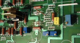
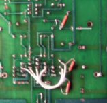
You are welcome. I just noticed that the picture in post #111 also shows where I cut the traces between Q7 and Q8 and similarly Q10 and Q11 to wire in the trimpots R32 and R33.
I'm going to order the last few parts today - mostly capacitors for the power supply. Hopefully I'll have a pair of boards finished to listen to next week 🙂
Phil
A few more observations on the Krill PCB. Again, these comments refer ONLY to the Krill 100W schematic posted in post #1013, page 41 of the “Krill - The little amp that might...”. This is the same schematic linked to in post #9, page 1 of the “Krill construction thread - 100W version”.
The large capacitors C22 and C23 are mislabeled (reversed) on the schematic. C22 is the filter capacitor for +50V. C23 goes to the -50V rail. They are labeled correctly on the 50W schematic.
There are 2 capacitors labeled C22 on the board. One is the large filter capacitor. The other capacitor labeled C22 is smaller and next to C16. This small “C22” (call it Cfb) can be used to AC-couple the feedback. There are two holes for the ground end of R10. One goes directly to ground. Use this for a DC-coupled amp. The other hole connects to ground through Cfb. (thanks to c2cThomas for pointing this out). A 220uF capacitor for Cfb will provide a corner frequency ≤1 Hz if you decide to AC-ground the feedback. Use more capacitance if you want.
D26 is the zener reference for Q18. It is labeled as ZD2 on the schematic. D25 (ZD1 on the schematic) is the zener for Q17.
jkeny said:Any reports from the front - build, measurements, sonics?
Hi JK - Phil H. is off for the weekend with his sweat heart, I'm building - one board finished except for some resistors that are due in Monday (or so), second board in process of slaughtering components on. I have not heard anything from Steve - so his status is undetermined at the present time. I know that a couple of new builders have received their boards and most likely are into build-up - but I don't know if they will post results or not. Some builders want to do just that - build and enjoy - and would just as soon avoid being splattered by the mess that sometimes goes flying about here. I'll be posting when I have my amps up - but mine are 50W versions so I'll most likely start a new thread about that version.

Thanks Thomas,
Hope all is well with family & dog!
I think the furore has calmed down since SD posted his sims so I hardly think there be any flac on this thread hopefully.
Thanks for the update - looking forward to hearing reports & final build instructions/corrections
Hope all is well with family & dog!
I think the furore has calmed down since SD posted his sims so I hardly think there be any flac on this thread hopefully.
Thanks for the update - looking forward to hearing reports & final build instructions/corrections
- Home
- Amplifiers
- Solid State
- Krill construction thread - 100W version