Yes. I'm working on this one as well and would like to know etsang3 where you set your bias mV? Also, did you ever get your's sounding right? Thanks
Yes. I'm working on this one as well and would like to know etsang3 where you set your bias mV? Also, did you ever get your's sounding right? Thanks
I would give it as much bias as possible without overloading the heatsinks. Yes I would most certainly exceed the bias that Krell would recommend. Krell would recommend a safe bias that will meet any and all amplifier placement criteria, i.e. warm rooms, components stacked on shelving, enclosed audio cabinets, etc. If my amp was sitting out by itself in the open in a cool room I would absolutely turn the bias up higher than factory recommendation as long as the heatsinks can handle it.
After increasing bias put the cover on and let it sit, if after an hour you can still keep your hand on the heatsinks for 10 sec then you're good. Then play music on your most difficult load loud speakers at a very high level for 30min, can you still hold your hand on the heat sinks? If not adjust the bias back down some and try again.
Last edited:
You may never get the factory recommended bias setting because Krell is tight lipped and probably going to tell you to send it to an authorized service facility. Due to this a small bit of experimentation should tell you within a few hours what the allowable bias range should be.
Start at 50mV of bias, put the cover back on and let it sit, check it in 30 min and see if the sinks are still stone cold, if so increase the bias a certain amount (probably +25mV) and let it sit again. Once the sinks start to get warm then decrease the increments that you increase the bias to +10mV or even +5mV. Repeat until you get the sinks to a level that they're nearly too hot to touch. If you have an IR temp gun that's even better you can record the temp curve vs bias and post it for everyone else that may read this thread in the future. Once you have this curve you can decide how high of a temperature that you want to operate the amp at.
Start at 50mV of bias, put the cover back on and let it sit, check it in 30 min and see if the sinks are still stone cold, if so increase the bias a certain amount (probably +25mV) and let it sit again. Once the sinks start to get warm then decrease the increments that you increase the bias to +10mV or even +5mV. Repeat until you get the sinks to a level that they're nearly too hot to touch. If you have an IR temp gun that's even better you can record the temp curve vs bias and post it for everyone else that may read this thread in the future. Once you have this curve you can decide how high of a temperature that you want to operate the amp at.
Thanks Chamberman for the tips. The one I'm working on after 30min I can't place my hand for more than 4 or 5 seconds. I'm going to do some maintenance and reset/check bias when I get done.
Chamberman is correct and safer approach.
I have tuned the amp to around 14W Class A and it is quite hot.
I maintain it should not exceed 75˚C or it will be unsafe. It is better to keep the temperature around 50˚C. 4 pairs of MJ15024/25 are used as output transistors and 1 pair of MJ15024/25 is used as the drivers for the power transistors. Since the idle current (bias) of the power transistors had been increased, the idle current of the drivers should also be increased or there will be cut off distortion when the amplifier at high level output.
I have changed the driver transistors' (E) resistors to 10Ω hence the idle current will be around 65mA. (see the attached photos)
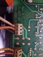
There is a PCB track mistake at my version, the 0.1uF bias bypass is with a floating leg so I add a wire to connect that leg to the bias transistor MJE15030 (C).
The 2 bias testing points provided at the PCB is actually connected to the 0.5Ω RE of the nearest power transistor MJ15025
BIAS-ADJ.jpg - Google Drive
bias_chart.jpg - Google Drive
I have tuned the amp to around 14W Class A and it is quite hot.
I maintain it should not exceed 75˚C or it will be unsafe. It is better to keep the temperature around 50˚C. 4 pairs of MJ15024/25 are used as output transistors and 1 pair of MJ15024/25 is used as the drivers for the power transistors. Since the idle current (bias) of the power transistors had been increased, the idle current of the drivers should also be increased or there will be cut off distortion when the amplifier at high level output.
I have changed the driver transistors' (E) resistors to 10Ω hence the idle current will be around 65mA. (see the attached photos)
There is a PCB track mistake at my version, the 0.1uF bias bypass is with a floating leg so I add a wire to connect that leg to the bias transistor MJE15030 (C).
The 2 bias testing points provided at the PCB is actually connected to the 0.5Ω RE of the nearest power transistor MJ15025
BIAS-ADJ.jpg - Google Drive
bias_chart.jpg - Google Drive
Excellent. Thanks for the info etsang3. When you give a temp of 75C is that at the near heatsink fin metal or is that on the to3 transistor cases? Ie. where would you point the temp gun to get your final temp?
I use a contact type electronics thermometer add a little bit heat transfer compound to touch the metal case of the power transistor.
At 75C, the junction inside will be 85C.
At 140 to 150C the power transistor will die immediately.
At 75C, the junction inside will be 85C.
At 140 to 150C the power transistor will die immediately.
I'm assuming no screw on the side so these are the spring loaded style. Slide a small flat screwdriver blade into the slot above the wire. The springs I've encountered are pretty tight so you may need to wedge the blade in there firmly to get the spring to release. Tug lightly on the wire while working the blade into the slot. The wire will probably still have some resistance but will eventually pull out of the slot.
Thanks! Yes no side screws on these. I did try what you are suggesting, but I did not get very strong with it for fear of damage. I tried the back side and above wire slots. Hopefully I can get it back in after removal!
These are just push in, get a small screwdriver pushed in the slots, and the leads will pop right out. And yes they are really tough
You know if it were mine I'd replace those spring loaded connector terminal blocks with the screw style. I hate those damn spring style ones and I don't really trust the connection either.
You know if it were mine I'd replace those spring loaded connector terminal blocks with the screw style. I hate those damn spring style ones and I don't really trust the connection either.
All the old Krells use them and they are very reliable.
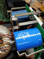
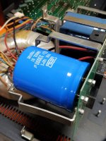
Hope you guys can help me. I was thinking these new United Chemi-Con screw caps would squeeze inside the "rails" that Krell used on this amp. I was wrong. I honestly can't find a screw style cap that will fit this amp. The new Vishay Sprague caps that cross-reference these old caps are not the same footprint; much taller. I can mount these Chemi-cons but as you can see from the pic they do not fit underneath the rails. They would be perfect if just a few milimeters shorter and didn't have the rear bolt (I was planning just to cut that off).
I welcome ideas!
I welcome ideas!
Attachments

- Home
- Amplifiers
- Solid State
- Krell KST-100 Amplifier