
Hi, I'm trying to build a ksa-50 on a delta-audio board. But I can’t figure out how to make two different voltages from one source. Couldn't find it on the forum. If anyone has a diagram of such a power supply, please post it.
It depends if you want to go "up" of "down" in voltage
To to up yo need some sort of voltage doubler but it may end to high for your needs.
To go down you just need a voltage regulator and in both cases there are plenty of diagrams/projects online.
I remember a project that used a small VA transformer to "lift" the voltage for the preamp stages but that was over 25 years ago and can't find it anymore.
Good luck
Can you be more specific please? Do you mean + and - voltages lower than the raw psu output as it sounds like you want + and - from a single (+ve) supply.Hi, I'm trying to build a ksa-50 on a delta-audio board. But I can’t figure out how to make two different voltages from one source. Couldn't find it on the forum. If anyone has a diagram of such a power supply, please post it.
I have two transformers, one per channel. voltage 230/ 36-0-36, 250W. and the question is whether it is possible to obtain two voltages from one such transformer. Probably someone assembled it using a delta audio circuit, pre stage voltage 50v, output stage 47v. I was hoping there was a ready solution.
Attachments
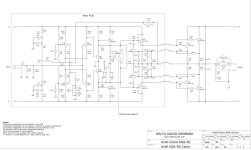
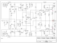
in your schematic, you separate Agnd with Vgnd, where is the source from ground output/speaker, thanks in advanceHere is my KSA50 schematic with voltage references if anybody is using a similar voltage. I am getting right at 50 watts/RMS/8 ohm load.
My KSA50 amps use +/- 33.5VDC, so in order to keep the zener diode circuit from possibly falling out of regulation, I am using 910R instead of 1k5 for R1 & R38. This allows approximately 7mA to flow through the circuit (3mA for the LTP and 4mA for regulation).
I also replaced the emitter follower (emitter resistors) R5 & R42 3k3 with 1k2. This allows approximately 1.3mA instead of 425uA to flow through the emitter follower.
Here is my latest schematic based on my power supply voltage. A few component values are optimized for my power supply voltages.
Some AP measurements as well.

1 Watt/8 Ohm

1 Watt/8 Ohm Frequency Response (Yellow) vs THD+N (Green)

Signal to Noise/1 Watt (8 Ohm reference)

5 Watts / 8 Ohm

Power out / 8 Ohm

Some AP measurements as well.
1 Watt/8 Ohm
1 Watt/8 Ohm Frequency Response (Yellow) vs THD+N (Green)
Signal to Noise/1 Watt (8 Ohm reference)
5 Watts / 8 Ohm
Power out / 8 Ohm
Thanks for the schematic and measurements! Do you have a printed circuit board? Or can I use a ready-made one from eBay?Here is my latest schematic based on my power supply voltage.
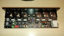
I bought two complete amp modules from eBay many years ago. I swapped out the semiconductors since I did not trust that they were probably Chinese fakes. The resistors & caps were fine.
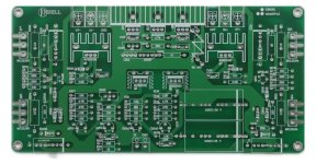
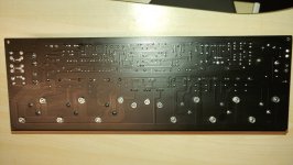
These appear to be good quality PCB's;

This is the PCB I bought:

These appear to be good quality PCB's;
This is the PCB I bought:
Translation:Ciao, hai ancora le istruzioni per i PCB KSA50 zona zero? Ho i PCB
Hi, do you still have the instructions for the KSA50 zero zone PCBs? I have the PCBs
Please write in English.
Hugo

Moderation team
Hello everyone 🙂
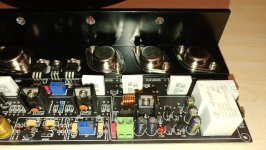
I bought the Chinese KSA 50 and I have a question about the quiescent current.
I have 2x 350W Transformer and 2x 6.5KG Radiator.
The manufacturer recommends setting the current to 1.2A, but does not specify whether it is for one PCB, a set or a single transistor.
So what should I set the quiescent current to?
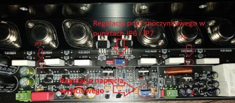
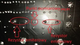
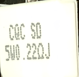
JP6 JP7 is the static current test point. The emitter resistor is 0.22 Ohm. What value in mV should be at these points? Alternatively, how much should the ammeter show on the main power terminals for one PCB?
I bought the Chinese KSA 50 and I have a question about the quiescent current.
I have 2x 350W Transformer and 2x 6.5KG Radiator.
The manufacturer recommends setting the current to 1.2A, but does not specify whether it is for one PCB, a set or a single transistor.
So what should I set the quiescent current to?
JP6 JP7 is the static current test point. The emitter resistor is 0.22 Ohm. What value in mV should be at these points? Alternatively, how much should the ammeter show on the main power terminals for one PCB?
Attachments
-
 20200423_191336_8481772.jpg422.9 KB · Views: 130
 -
 20200423_191349_1376915.jpg363.5 KB · Views: 132
 -
 20200423_191412_5072766.jpg338.7 KB · Views: 119
 -
 20200424_131908_jpg_c7114f4866881203786369116edbb4e8_1374624.jpg288.8 KB · Views: 107
 -
 20200425_132524_jpg_a7bb7b194ae5826cc63e7427395cf242_7859319.jpg258.9 KB · Views: 101
 -
 485391628_Screenshot_20200424-2300492_png_7514a774cd8c49a42f220de7f564317b_2095241.png98.3 KB · Views: 118
I have the same design and set the current to .45a per transistor - 1.35amps - ie. 100mv.
No way can you have 1.2amps per transistor, they will not take it.
No way can you have 1.2amps per transistor, they will not take it.
I measured between one (can't remember which) and the speaker out for both plus and minus test points. On one of my amps boards, the voltages were not the same.
The Delta Audio boards have switchable bias- is this what you are talking about? So its not two voltages from one source but two levels of bias (low or high).Hi, I'm trying to build a ksa-50 on a delta-audio board. But I can’t figure out how to make two different voltages from one source. Couldn't find it on the forum. If anyone has a diagram of such a power supply, please post it.
Is this what you mean?
Also are you aware of the errors on those boards?
Last edited:
- Home
- Amplifiers
- Solid State
- Krell KSA 50 PCB