2 more
Hi troy,
Just sent you my payment for 2 kits + shipping. I will e-mail you later in order to provide you all the info needed fo th shipment.
Thank you,
Loris
Hi troy,
Just sent you my payment for 2 kits + shipping. I will e-mail you later in order to provide you all the info needed fo th shipment.
Thank you,
Loris
I just paid up for two channels too.
Now to source transformers... Any body know of some good toroid deals?
I got a quote from thermaflo for some heatsink extrusions, and all I have to say is holy cow for their 0.18c/w efficient extrusion E1365 is $273 each. 27" wide x 3" tall (with 2.7" fins)
I guess forced convection is the only way to go on a budget
~Brad
Now to source transformers... Any body know of some good toroid deals?
I got a quote from thermaflo for some heatsink extrusions, and all I have to say is holy cow
for their 0.18c/w efficient extrusion E1365 is $273 each. 27" wide x 3" tall (with 2.7" fins)I guess forced convection is the only way to go on a budget
~Brad
googler said:
I guess forced convection is the only way to go on a budget
~Brad
I don't know how tight your budget is, but you could look at Conrad model MF35-151.5, with or without flanges.
http://www.conradheatsinks.com/products/flat100_350.html#MF35
Shipping from Australia is a bit expensive, but you could lower your final cost if you find more people to buy heatsinks with you.
Hi guys,
Is there a new BOM for the Pink Mouse boards. On the new boards I have spots for C401-C404. No such critters on the Delta Audio BOM. Also, what happened to C107 & C108? Where did C303 and C304 come from. Have I missed something along the way?
Thanks, Terry
Is there a new BOM for the Pink Mouse boards. On the new boards I have spots for C401-C404. No such critters on the Delta Audio BOM. Also, what happened to C107 & C108? Where did C303 and C304 come from. Have I missed something along the way?
Thanks, Terry
Hi Terry
C401/4 and C301/4 are optional rail decoupling caps, 100uf (ish)50V with .01uf bypassing. You don't need to use them if you don't want to and the originals didn't have them, but they will help PSRR, especially with the split board design.
C107/8 are not needed, but if you want them, you can just tack them on underneath the board.
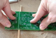
Well as the first part of the builders guide I promised, here is a pic showing the best way I have found of splitting the boards up. Push on one side, then repeat on the other, and the boards will snap cleanly. Much less fuss than saws or knives.
C401/4 and C301/4 are optional rail decoupling caps, 100uf (ish)50V with .01uf bypassing. You don't need to use them if you don't want to and the originals didn't have them, but they will help PSRR, especially with the split board design.
C107/8 are not needed, but if you want them, you can just tack them on underneath the board.
Well as the first part of the builders guide I promised, here is a pic showing the best way I have found of splitting the boards up. Push on one side, then repeat on the other, and the boards will snap cleanly. Much less fuss than saws or knives.
Attachments

Hi Still4given,
the extra C303/4 (on the schematic) & C401-4 (on eagle & PDF) are, in my opinion, essential not optional.
You could go as low as 100uF but I recommend 470uF as shown or bigger if you can find pin pitch to fit. The bypass are shown as 100nF (0.1uF) but the smaller size may be OK.
C107/8 simply become extra base/collector load for the two drivers (Q107/8) and should not be necessary, unless someone says they are needed for some pole splitting/other reason.
Pinky,
how about supporting all four corners of the driver board?
AndrewT said:Pinky,
how about supporting all four corners of the driver board?
I thought about that, and if these amps were going on the road I would, but as it is, with the metal spacers and the thickness of the boards, the assembly is very rigid.
Am glad to see that boards I shipped last Saturday are arriving ok. Al, You must have stayed up all night after those arrived!
Mark
Mark
Hi guys,
OK, thanks for the info. I will probably go ahead and add them if they are not going to change the audio. I probably have some caps here that will work. Where can I find the eagle files? I wish I had DL'd them before, it would have saved me asking these questions now.
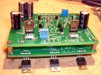
Al. I noticed you didn't use the 2SC3955 for Q111. What was the reason for that and what did you use? I suppose it doesn't matter now since I already have the parts but I had to go to another source for those and that added to my shipping. 🙁
I didn't mount the drivers or Q111 like you did, I mounted them straight up figuring to use a common heatsink for them and get the thermal tracking that way. Has anyone tried that yet? It was mentioned earlier in the thread. I thought about doing it the way you have and may change it. I am still trying to figure out how to work the heatsinks. I would like to have everything on the main heatsinks.
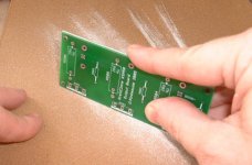
This will probably sound silly but I thought I'd share the way I snapped the boards. Here goes.
When the door to my studio is closed there is just enough room to slide the board between the door and the jamb. I simply slid the end of the board that needed to be removed into the gap between them and pushed sideways on the board. Snaps it off very easily and the wood door/jamb is soft enough to not harm the board in any way. Just thought I would pass that on.
Note: You don't have to have a studio, just about any door will do. 😉
One more thing I noticed. I used 1/4w Dales for just about everything. The few places that I used 1/2w Dales, it was very tough to get them in. The holes are very tight on the leads and the hole spacing is barely wide enough. You guys who are doing the Parts Group Buy might want to check this before you leap.
It could just be the 1/2w resistors that I had but the 1/4W 1% Dales I used are a very good fit.
Blessings, Terry
OK, thanks for the info. I will probably go ahead and add them if they are not going to change the audio. I probably have some caps here that will work. Where can I find the eagle files? I wish I had DL'd them before, it would have saved me asking these questions now.
Al. I noticed you didn't use the 2SC3955 for Q111. What was the reason for that and what did you use? I suppose it doesn't matter now since I already have the parts but I had to go to another source for those and that added to my shipping. 🙁
I didn't mount the drivers or Q111 like you did, I mounted them straight up figuring to use a common heatsink for them and get the thermal tracking that way. Has anyone tried that yet? It was mentioned earlier in the thread. I thought about doing it the way you have and may change it. I am still trying to figure out how to work the heatsinks. I would like to have everything on the main heatsinks.
This will probably sound silly but I thought I'd share the way I snapped the boards. Here goes.
When the door to my studio is closed there is just enough room to slide the board between the door and the jamb. I simply slid the end of the board that needed to be removed into the gap between them and pushed sideways on the board. Snaps it off very easily and the wood door/jamb is soft enough to not harm the board in any way. Just thought I would pass that on.
Note: You don't have to have a studio, just about any door will do. 😉
One more thing I noticed. I used 1/4w Dales for just about everything. The few places that I used 1/2w Dales, it was very tough to get them in. The holes are very tight on the leads and the hole spacing is barely wide enough. You guys who are doing the Parts Group Buy might want to check this before you leap.
It could just be the 1/2w resistors that I had but the 1/4W 1% Dales I used are a very good fit.
Blessings, Terry
Hi Terry
I used another 15032, (but I have also used 15030 with no problems), for Q111. The 2SCs were impossible to get in the UK in quantities of less than 500. As for the resistors, I picked a pin spacing that would cope with most types of resistor, yet without using up too much space on the board. Be greatful I didn't chose those subminature ones that some other people like! 🙂
Which particular Eagle files are you after?
Mark
Thanks for the prompt despatch!
The boards had arrived when I got home on Thursday night, so I had a quick play around yesterday. I had most of the bits still in stock, it's only the resistors that I need to think about really, so progress to those photos only took an hour or so.
I must admit, I am very pleased with the pcbs, you did an excellent job getting that end together. Well done.
pinkmouse said:Hi Terry
I used another 15032, (but I have also used 15030 with no problems), for Q111. The 2SCs were impossible to get in the UK in quantities of less than 500. As for the resistors, I picked a pin spacing that would cope with most types of resistor, yet without using up too much space on the board. Be greatful I didn't chose those subminature ones that some other people like! 🙂
Which particular Eagle files are you after?
Mark
Thanks for the prompt despatch!
The boards had arrived when I got home on Thursday night, so I had a quick play around yesterday. I had most of the bits still in stock, it's only the resistors that I need to think about really, so progress to those photos only took an hour or so.
I must admit, I am very pleased with the pcbs, you did an excellent job getting that end together. Well done.
Hi Al,
I wish I had known that about Q111. I have plenty of 15030's or 15032's. What is the reason that the 3955's were called out there if we could use a part that was already on the list?
I see that you haven't yet installed your resistors. Do you have any 1/2w Dales laying around that you could trial fit in there. You will see what I'm talking about. The 1/4w Dales are a good fit but the 1/2w Dales that I have are too tight IMO. Please try to check that before they order the GB. To me, if 1/4W works just as well, fighting the 1/2w units doesn't make sense.
My $.02
Blessings, Terry
still4given said:I wish I had known that about Q111. I have plenty of 15030's or 15032's. What is the reason that the 3955's were called out there if we could use a part that was already on the list?
Wasn't me guv, I've always been using the Motorolas...
To me, if 1/4W works just as well, fighting the 1/2w units doesn't make sense.
I don't have any at present. Could you post a pic of the problem area?
The Sanyo's are very fast and have a plastic suit, easier mounting.
The reasons PM suggested the SC3955.
After my mishap with MCM, i ordered the Sanyo's from Nikko's, should teach me to be less of a scrooge.
(still chewing MCM's rubber belts for breaky)
The reasons PM suggested the SC3955.
After my mishap with MCM, i ordered the Sanyo's from Nikko's, should teach me to be less of a scrooge.
(still chewing MCM's rubber belts for breaky)
Dalbani for UK 2sc & 2sa
Hi UK listeners,
I have used http://www.dalbani.co.uk for all my recent transistor purchases. Excellent service, and very good prices. Back order on one out of stock item came with no extra carriage charges.
Hi UK listeners,
I have used http://www.dalbani.co.uk for all my recent transistor purchases. Excellent service, and very good prices. Back order on one out of stock item came with no extra carriage charges.
Re: Dalbani for UK 2sc & 2sa
Even to Holland.
AndrewT said:Back order on one out of stock item came with no extra carriage charges.
Even to Holland.
pinkmouse said:
Wasn't me guv, I've always been using the Motorolas...
I don't have any at present. Could you post a pic of the problem area?
I wish I had thought of that. I'm at work now but will try to do it tonight when I get home. The only place I used an actual 1/2w Dale was for R101 and the resistor is actually a tad longer than the spacing causing the leads have to wrap back under the resistor a tad. I had already decided to use 1/4W, and that is what I ordered. I only used 1/2W for where .6W was called out And in those cases I used some non-Dale 1% metal film resistors that I had on hand. The only reason I used the 1/2W Dale for R101 is because I got the wrong value when I ordered and had the Dale in my bone pile. The worst part is that the holes are a very, very snug fit on the leads for a 1/2W. If there is any kink at all in the lead it will not slide easily through the hole. I almost pulled the plating out trying to help the wire through with some pliers.
It would be great if someone else who has received their boards could try some 1/2w Dales in them to verify what I've experienced. Maybe the 1/2w resistors that I have are not typical but I doubt it.
Blessings, Terry
I must admit, the holes do seem a little tighter in the thicker production boards than they were on the prototypes. I was aware that they slightly shrink back after drilling, but the thicker FR4 we used seems to display this to a greater extent . Something to bear in mind for the next pcb design I suspect.
- Home
- Amplifiers
- Solid State
- Krell KSA 50 PCB