Hey, thanks guys!
Yes, I'm using the 2SC3955. So does that mean I can just use the silicon grease?
Thanks, Terry
Yes, I'm using the 2SC3955. So does that mean I can just use the silicon grease?
Thanks, Terry
Re: the CCS...
Let me know how much I need to contribute financially.
🙂
Stuart Easson said:...really isn't necessary, I don't think it adds value in the normal design, though I don't have any listening tests to justify it's inclusion or exclusion...
It didn't show up in Krell designs until a later version, where it appeared in the front end, then later went away to reappear in the Vas...which also became mosfet based...
I will make PCBs for anyone that wants them, so unless there is really no overhead finanically and very little timewise, I vote to leave it off GB board.
There are other things I want to investigate (better CCS, current mirrors, front end regulation?, dual slope VI limiter) etc. I will update everyone as these things evolve and if they are useful, make a bigger small board...
Stuart
Let me know how much I need to contribute financially.
🙂
I think the other posters who recommended ways to insulate must have momentarily forgot that this is the specified part and that it is encapsulated and needs no special mounting insulation. At least the ones I have don't.
Indeed, I rarely use any foreign transistors myself for any of my projects, I prefer to keep it "All American" when ever and where ever I can, hence the need for insulators on everything.
Go ahead and slap er right down with some grease Terry, no need for the insulator except on the drivers and outputs!
Mark
Mark A. Gulbrandsen said:
Indeed, I rarely use any foreign transistors myself for any of my projects, I prefer to keep it "All American" when ever and where ever I can, hence the need for insulators on everything.
Go ahead and slap er right down with some grease Terry, no need for the insulator except on the drivers and outputs!
Mark
Awsome!
OK then.
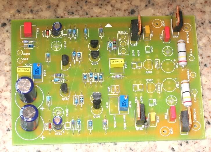
Here's one of my boards stuffed with those tiny 1/2w resistors. I still waiting on the Zeners.
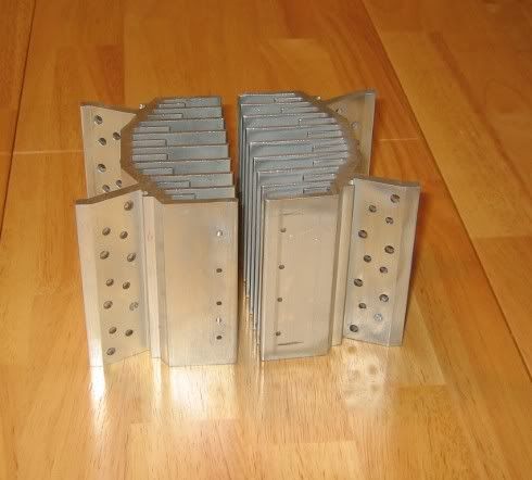
And here are the heatsinks I'm planning to use.
Blessings, Terry
Here's one of my boards stuffed with those tiny 1/2w resistors. I still waiting on the Zeners.
And here are the heatsinks I'm planning to use.
Blessings, Terry
Mark,
When does the WIKI close? Wasn't it today?
The numbers have remained at around 150 for a couple of weeks now so I think all those that are in have their name down.
The reason I'm badgering you is because I've virtually finished my speaker project and am really waiting on the amps or will be within the next couple of weeks.
In other words can I give you some money? 😀
Hi,
the first version of Krell Klone used a 2sc3955 for the Vbe multplier.
Can someone confirm which characteristics are used to determine a suitable transistor for the multiplier?
The reason I ask is that the 3955 has by far the highest Vce0 and the highest Ft compared to ALL the other transistors in the build up and this seems an odd choice bearing in mind the earlier comments regarding using similar speed transistors throughout the Klone.
I think people are too concernbed about what transistors to use. This amp is not high speed stuff and transistor selection is not all that critical and is not going to be all that noticable, if at all even audible.
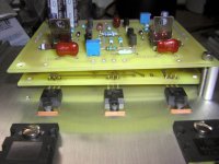
Terry's heat sink is about the same size as the original KSA-50 sink so he's right on the money there. You may want to mount the drivers and bias sense on the main sinks, if not you will need pretty large sinks for those drivers. Anyway, go for it Terry! The new boards can be stacked like this and all it takes is very short jumpers to connect the two together. his makes mounting the drivers alot easier than on Jan's board. See Photo below and also notice the broken tap in the heatsink .
.
Group Buy
As for the group buy I am waiting on Al to do the changes to the holes to allow larger wire and there is some debate as to the CSS board being added onto this board to keep that cost down. I am not all that interested in the CSS for myself so you guys fight that one out and let me know. When I receive the new files fomr Al then I can contact Advanced and barter with them to get the changes though at the same price(hopefully) or not too much of an increase.
Mark
Terry's heat sink is about the same size as the original KSA-50 sink so he's right on the money there. You may want to mount the drivers and bias sense on the main sinks, if not you will need pretty large sinks for those drivers. Anyway, go for it Terry! The new boards can be stacked like this and all it takes is very short jumpers to connect the two together. his makes mounting the drivers alot easier than on Jan's board. See Photo below and also notice the broken tap in the heatsink
.Group Buy
As for the group buy I am waiting on Al to do the changes to the holes to allow larger wire and there is some debate as to the CSS board being added onto this board to keep that cost down. I am not all that interested in the CSS for myself so you guys fight that one out and let me know. When I receive the new files fomr Al then I can contact Advanced and barter with them to get the changes though at the same price(hopefully) or not too much of an increase.
Mark
Attachments
I have been following this thread and joined the Wiki because I am interested in building a KSA-50 clone. If the design is modified and departs from the original Krell schematic, I will be discouraged to purchase the boards.
I would, however, be interested in purchasing power supply boards like this one:
http://www.diyaudio.com/forums/showthread.php?postid=323066#post323066
If enough people are interested, I would not mind organizing a group buy.
I would, however, be interested in purchasing power supply boards like this one:
http://www.diyaudio.com/forums/showthread.php?postid=323066#post323066
If enough people are interested, I would not mind organizing a group buy.
Actually the power supply board we are able to offer is the one that Brian GT designed for the Aleph series. From my experience its a nicer board than the one in the link and I believe has either 3 or 4 oz copper.
Mark
Mark
parts avail
Terry, I've used 5W zeners after realizing that I bought 2W ones that did not match the 3W spec. Guess I should have posted like you, and I would have learned that the wattage rating did not matter; but now I've got these extra, if you want them they are yours, free. If you need any other parts, just let me know; but looking at your board looks like you are pretty much set (if not just email or post). I just can't see myself using these 27V zeners in any other project.
I've got 3 extra soft start boards (see my link below); if anyone wants one just email me.
still4given said:OK then.
Here's one of my boards stuffed with those tiny 1/2w resistors. I still waiting on the Zeners.
Blessings, Terry
Terry, I've used 5W zeners after realizing that I bought 2W ones that did not match the 3W spec. Guess I should have posted like you, and I would have learned that the wattage rating did not matter; but now I've got these extra, if you want them they are yours, free. If you need any other parts, just let me know; but looking at your board looks like you are pretty much set (if not just email or post). I just can't see myself using these 27V zeners in any other project.
I've got 3 extra soft start boards (see my link below); if anyone wants one just email me.
GeWa said:Looking good so far Terry. BTW, what's the height of that heatsink?
Regards
The heatsinks are 4 1/4" in length and use a 5" dia. fan. They are designed to cool a P500, which is 250wpc AB. I'm hopeful they will be enough.
Terry's heat sink is about the same size as the original KSA-50 sink so he's right on the money there. You may want to mount the drivers and bias sense on the main sinks, if not you will need pretty large sinks for those drivers. Anyway, go for it Terry! The new boards can be stacked like this and all it takes is very short jumpers to connect the two together. his makes mounting the drivers alot easier than on Jan's board. See Photo below and also notice the broken tap in the heatsink .
I didn't think about the drivers being on the main sinks. I suppose I can do that. I was kind of hoping to keep the wires to a minumum. I have some heatsinks for the drivers but I don't know what you mean by "pretty large".
lgreen,
Thanks for the kind offer but I have already ordered the zeners from Mouser and onsemi so I think I've got them covered. I ordered the TO3 mounting sockets so when they get here I'm sure I'll have some more questions about wiring the outputs.
Thanks everyone, Terry
Any chance, you could link to a PDF with the softstart board? For selfetching, ofcourse😉I've got 3 extra soft start boards (see my link below); if anyone wants one just email me.
And the BOM would be nice,too.
Steen.🙂
progress...
1. Soft Start
Softstart- when I said check below- its the www link below my signature. The info is here. Parts are on the schematic on the link; I have extra Q's. too. I could give you EAGLE or pdf files, not sure on the pdf, but if you want the data, just email me off line.
Well, I happily worked on this all day. I've got a lot of compartments, wire gong everywhere; but making progress slowly.
I carefully filed, sanded and used epoxy on the holes between sections to avoid jagged metal edges.
Also, I didn't like the nasty cold rolled steel-- a little rusty too. So painted:
My Krell clone has interior compartments separated by cold rolled steel for ferromagnetic and electromagnetic shielding. The steel looks horrible with my sharpie writing all over it (noting orientation, holes etc...) No longer, compartments will be Ferrari Yellow -- On the inside! Hey- it was in my "parts box"...yeah right.
Also, wired up the front end power supply and soft start using the big caps (CL-60 shunted after a 7 sec delay). Tested and working thank goodness. But I've got some QUESTIONS.
Question - do you put thermal grease under the full wave bridge rectifier (shown) or just clamp it to the bottom plate?
(those are pathetic little tiny ventalitation holes for the front end you see in the pic with nothing connected-- yeah, go ahead and start talking about wind noise....)
Question- this will be a massive high current device- I've wired the main PSU caps and all high current paths with 14 gauge wire. Is this big enough? (I only ask because my transformer secondaries are 12 gauge wire and I suddenly feel like I am ripping myself off).
1. Soft Start
Any chance, you could link to a PDF with the softstart board? For selfetching, of course
And the BOM would be nice,too.
Softstart- when I said check below- its the www link below my signature. The info is here. Parts are on the schematic on the link; I have extra Q's. too. I could give you EAGLE or pdf files, not sure on the pdf, but if you want the data, just email me off line.
Well, I happily worked on this all day. I've got a lot of compartments, wire gong everywhere; but making progress slowly.
I carefully filed, sanded and used epoxy on the holes between sections to avoid jagged metal edges.
Also, I didn't like the nasty cold rolled steel-- a little rusty too. So painted:
An externally hosted image should be here but it was not working when we last tested it.
My Krell clone has interior compartments separated by cold rolled steel for ferromagnetic and electromagnetic shielding. The steel looks horrible with my sharpie writing all over it (noting orientation, holes etc...) No longer, compartments will be Ferrari Yellow -- On the inside! Hey- it was in my "parts box"...yeah right.
Also, wired up the front end power supply and soft start using the big caps (CL-60 shunted after a 7 sec delay). Tested and working thank goodness. But I've got some QUESTIONS.
An externally hosted image should be here but it was not working when we last tested it.
Ferrari yellow out of the parts bin.
Question - do you put thermal grease under the full wave bridge rectifier (shown) or just clamp it to the bottom plate?
(those are pathetic little tiny ventalitation holes for the front end you see in the pic with nothing connected-- yeah, go ahead and start talking about wind noise....)
Question- this will be a massive high current device- I've wired the main PSU caps and all high current paths with 14 gauge wire. Is this big enough? (I only ask because my transformer secondaries are 12 gauge wire and I suddenly feel like I am ripping myself off).
Try the calculator half way of this page and judge for yourself :
http://www.bcae1.com/wire.htm
Think of the number of turns of secondary wires and resulting length on a transformer !
Rectifier blocks are bolted to the chassis for cooling, grease wil improove performance.
Holes ? I dont see any holes.
http://www.bcae1.com/wire.htm
Think of the number of turns of secondary wires and resulting length on a transformer !
Rectifier blocks are bolted to the chassis for cooling, grease wil improove performance.
Holes ? I dont see any holes.
jacco vermeulen said:Try the calculator half way of this page and judge for yourself :
http://www.bcae1.com/wire.htm
Think of the number of turns of secondary wires and resulting length on a transformer !
Rectifier blocks are bolted to the chassis for cooling, grease wil improove performance.
Holes ? I dont see any holes.
Great link. My wire now looks fine. Thanks; I might put the link on the wiki.
Rectifier blocks don't need very much cooling--- so I have heard, but this is the 1st time I'm using a them vs. discrete diodes; but I suppose a little grease cannot hurt.
You can't see the holes---they are RIGHT THERE-- took me a long time to drill a bunch of those tiny bast**rds😉 I grouped them in 3's mostly so I would know not to connect stuff there.
rectifiers...
...to a simple approximation, dissipate about 3w per ampere,
If your idle current is at approx. 2A, your rectifiers are dissipating 6w, so they definitely need to be heatsunk...this power level will increase considerably if the amp drives lower impedance loads...by the time we get to the full power into 1 ohm scenario described yesterday, the rectifiers will be dissipating nearly 100w...go with the silicon heatsink compound too.
Stuart
- Home
- Amplifiers
- Solid State
- Krell KSA 50 PCB