rabstg said:Damping factor of 500 is normal. Slew rate it is not.
Damping factor of 500 is pretty good, 200 is more in the normal rage. The older krells were 160 to 200.
K-amps said:Damping factor of 500 is pretty good, 200 is more in the normal rage. The older krells were 160 to 200.
100 is good, 200 is pretty high.
KSA100:
50Hz - 172
150Hz- 175
1KHz - 178
10KHz- 168
(twice as high as the contemporary Threshold S300 seriesII)
jacco vermeulen said:
100 is good, 200 is pretty high.
Jacco, quit squinting when you think.
😉
i am cross-eyed, no need to rub it in !
The mailman just delivered 0.68Ohm Panasonic resistors from Stuart Easson.
These are axial-lobbed metalwire types, if you hold it in front of a strong lightbulb you'll see a meandering shadow.
Means inductance of these resistors is indeed very low, heat will be very evenly distributed across the surface.
This type of resistor is comparable with the MPC metalband resistors produced by Fukushiwa Futaba:
www.Fu-Futaba.co.jp
The resistance piece of MPC's however, is not a wire but a curved shape punched out of a thin special alloy metal plate
Anyway, wonderfull emitter resistors for the Krell, i think.
jacco vermeulen said:
100 is good, 200 is pretty high.
KSA100:
50Hz - 172
150Hz- 175
1KHz - 178
10KHz- 168
(twice as high as the contemporary Threshold S300 seriesII)
Please see slew rate and damping factor on the URL below. I've owned the 3b and 4b. Both excellent amplifiers... I could live happily with either of them again..
http://bryston.ca/pdfs/4bsst_spec.pdf
Hi!
This is Programmable series of the KSA-80 wich can be bridged into KSA-160. Damping factor 800, 20Hz-20kHz; slew rate 500 V/us. Maybe it's mistake, i don't know. I also think that is too high. In brochure for KSA-100S, KSA-200S and KSA-300S slew rate is 100 V/us.
Regards🙂
This is Programmable series of the KSA-80 wich can be bridged into KSA-160. Damping factor 800, 20Hz-20kHz; slew rate 500 V/us. Maybe it's mistake, i don't know. I also think that is too high. In brochure for KSA-100S, KSA-200S and KSA-300S slew rate is 100 V/us.
Regards🙂
Add to Wiki
If you guys have agreed to some of these original Krell specifications, can you post them in Chapter 4 of the Krell Build Wiki?
Thought someone was going to put a link to a review or two in there as well.
Whatever specs there are should be put in there so that a complete set can eventually be seen by all. I'd even put in basic specs like weight, size, 50 WPC, etc...
I spent some time yesterday inserting and linking posts from this thread (setting bias, heatsinking, etc...) into the wiki; please add to the wiki when good info comes up.
Splendid idea, Igreen. It would be nice to have all the important information in the "Build Wiki". It would be so much easier, compared to study and "filter" this long thread😉Whatever specs there are should be put in there so that a complete set can eventually be seen by all. I'd even put in basic specs like weight, size, 50 WPC, etc...
Thanks for your efforts to maintain the wiki😎
Steen🙂
I made a few class A amps and headphone Class A amps, and they all sounded better with a regulated supply. If there was any supply noise/hum, the regulated supply really takes care of it🙂What would the advantages be in doing this?
I am not sure that if you want to run the Krell with lowish bias, that the advantage will be so great. There has been a lot of talk about regulated supplies, not being the best for class A/B. Nonetheless, with the Zen amps and headphone amps I tried it, it was a great thing. They went totally quiet 🙂
Steen🙂
newer model
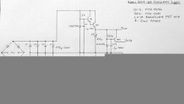
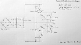
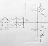
AFAIK The power supply board you show is from the 3rd and later version of the krell KSA series. It has higher regulated rails for the main board to make the 'new' driver topology work properly. The predrivers are mosfets and need a higher voltage to do their work.
If you have transformers wth additional windings it would be quite inexpensive to try, but you need about 10 more volts to feed the regulators...it would be easy to add additional windings on toroids with open centers...I may have to try it later...
It's not clear any benefit will accrue in the earlier amps...as long as the voltage doesn't droop below that required for the zeners in the front end...
Stuart
Do any of the transistors in the earlier design boards require matching? If so how do I accomplish this?
Regards
Anthony
Regards
Anthony
matching & regulating
Hum in the Zen is more of a problem than in the krell. From my simplistic tests The KSA50 has an ok PSRR (>30db), this combined with huge caps makes hum a non-issue, or at least that induced from the rails...
If you want to match, I think the input pairs are the best candidates, since any differences there are amplified through the rest of the amp.
To do the matching in the trivial sense, you could use a meter with an Hfe range, for instance to make sure the twins of the LTPs are close. After that, you'd need to build a test jig, to check the current gain and Vbe at the target Ic...and if you really wanted to get serious, then you could do a real transfer function plotter, which would show the transfer characteristic for a range of voltages and currents.
If you intend to literally match the transistors, don't forget to apply the same matching criteria to the components that control the operating points of those transistors...ie don't spend the time effort and money to get a set of <1% outputs unless you do the same with the emitter resistors...don't exactly match LTP pairs unless you do all the resistors that surround them...Really if you've got 2% passives there is no point in having 0.5% semis...
So far the 32 outputs I am using are sharing current equally to better than 10% with no matching of anything.
Stuart
Re: matching & regulating
So I might as well just bodge in any old devices as I have no emotional attachment to this Amp. I just want to get the bloody thing off my bench! 🙂 🙂
Anthony
Stuart Easson said:Hum in the Zen is more of a problem than in the krell. From my simplistic tests The KSA50 has an ok PSRR (>30db), this combined with huge caps makes hum a non-issue, or at least that induced from the rails...
If you want to match, I think the input pairs are the best candidates, since any differences there are amplified through the rest of the amp.
To do the matching in the trivial sense, you could use a meter with an Hfe range, for instance to make sure the twins of the LTPs are close. After that, you'd need to build a test jig, to check the current gain and Vbe at the target Ic...and if you really wanted to get serious, then you could do a real transfer function plotter, which would show the transfer characteristic for a range of voltages and currents.
If you intend to literally match the transistors, don't forget to apply the same matching criteria to the components that control the operating points of those transistors...ie don't spend the time effort and money to get a set of <1% outputs unless you do the same with the emitter resistors...don't exactly match LTP pairs unless you do all the resistors that surround them...Really if you've got 2% passives there is no point in having 0.5% semis...
So far the 32 outputs I am using are sharing current equally to better than 10% with no matching of anything.
Stuart
So I might as well just bodge in any old devices as I have no emotional attachment to this Amp. I just want to get the bloody thing off my bench! 🙂 🙂
Anthony
Stuart,
What might be interesting to try out would be to combine your CSS on the front end with the first part of the regulator set to say 40 volts DC to just the main board. An entirely different and inexpensive transformer could be used to power this supply,although I agree windings could be added.... just the extra isolation you might gain from a seperate. Gee, I wonder if we could get Al to combine all this into one new Main board😀 .
I've also found quite a close match on current sharing from the output devices I bought from MCM... having all the same lot code seems to be the more important aspect.
Mark
Attachments
emotional attachment...
Please don't take my comments to mean you shouldn't match if you want to...heck I arrange all my resistors so the tolerance band is on the same side...
My point was more that I think you'll get more back from your investment of time by making a superb enclosure, perfectly finished, than by matching semis, especially if you only focus on a single aspect of the matching. Spend the money saved by not needing dozens of extra outputs on a bigger transformer or caps...you know the sort of stuff...
If matching is worth doing, it has to be worth doing all the components necessary so the chunks of circuit concerned really are matched...
I find the transition from loose PCBs to an enclosed amp, ready to work, safe for the houshold etc the point at which I find emotional attachment beginning to form...until then my project is subject to all the indignities any prototype may have heaped on it...
Stuart
Maybe next year...
Mark, if you need to contact me, use the work email I sent you a week or so ago.
Mark, if you need to contact me, use the work email I sent you a week or so ago.
Mark A. Gulbrandsen said:What would the advantages be in doing this?
In the MPSA version a 1mA variance in the VAS stage would result in a voltage difference of 3.4 Volts.
With minimum hFe of the mpsa's at 25, current variance at the collector of the LTP device need only be 1/25th mA.
Voltage regulation of the LTP and VAS rails give accurate working points, resulting in less hard labor for the feedback to rectify the mistakes.
Less work for the feedback should improve sound, if the feedback is constantly correcting the output signal is never perfect.
(my opinion anyway)
I found a box full of 2* 9 VAC sealed toroidal transformers on the web for $1 each. (surplus telephone transformers), using those to raise the PS voltage to regulation level.
The regulator for the 80/160 is a bit simple, but changing it to KSA50 level is easy.
Would do very nicely on the Krell clone, i think.
- Home
- Amplifiers
- Solid State
- Krell KSA 50 PCB