Wim, you are quite entitled to have your opinions, and indeed to voice them. 🙂
I initially never intended this to be another GB, I was making the boards purely for myself as I had missed out on Jan's. However, people wanted to buy them...
Nice looking setup, L! I wouldn't worry too much about the live heatsinks as you will all be cased up, you just need to be a bit careful with the screwdriver during testing.
tabs
I think I understand what those little tabs are supposed to do, never thought that such a thing existed. Then again, i'm still new at this.
Can you post a pic when you find one, or name of manufacturer?
Wim- express your opinions all you want especially since I'm the "other reader" that you agree with!
To lgreen
I have to agree with Upupa. Make the holes bigger to get better efficiency and reduce flow noise. I'm going to do a similar setup on my amp, the only difference will be that my fan will be on the bottom of the heatsink blowing air up trough the sinks.
Regards
I have to agree with Upupa. Make the holes bigger to get better efficiency and reduce flow noise. I'm going to do a similar setup on my amp, the only difference will be that my fan will be on the bottom of the heatsink blowing air up trough the sinks.
Regards
It seems to me, that even with 16 outputs we're only talking about drilling out 32 holes. Couldn't take but a few minutes with a sharp bit. It's not like you have to do any layout or anything. Then you could use standard T03 sockets if you want to. I know the threads in the heatsink make an easy attachment but if you are worried about live heatsinks, drilling out the holes would be very simple IMHO.
The heatsinks I'm planning on using are very similar to those pictured but shorter in length and drilled for three outputs per "wing".
Blessings, Terry
The heatsinks I'm planning on using are very similar to those pictured but shorter in length and drilled for three outputs per "wing".
Blessings, Terry
holes
Ok, I'm going to use those little dealies and insulate the output devices. More parts to get but it will make me feel much better.
I have to admit, I didn't know what he was talking about. What holes? I was going to drill additional but smaller holes where the little dots are in the attached pic......
I understand more is better. But this looks good to me, I think people here get carried away with the number of vent holes so Imight try it like this and see what temp I end up with... then again those little dots are calling me....
The sink is 1" higher than the bottom plate, not flush, so I thought this would be ok for ventilation...it took me a half day of drilling as the base is very thick aluminum.
Hey, the holes are mostly lined up, but these won't be visible so I didn't care.
The top will be completely cut open with a fine mesh grill.
Is this enough?
Ok, I'm going to use those little dealies and insulate the output devices. More parts to get but it will make me feel much better.
To lgreen
I have to agree with Upupa. Make the holes bigger to get better efficiency and reduce flow noise. I'm going to do a similar setup on my amp, the only difference will be that my fan will be on the bottom of the heatsink blowing air up trough the sinks.
I have to admit, I didn't know what he was talking about. What holes? I was going to drill additional but smaller holes where the little dots are in the attached pic......
An externally hosted image should be here but it was not working when we last tested it.
I understand more is better. But this looks good to me, I think people here get carried away with the number of vent holes so Imight try it like this and see what temp I end up with... then again those little dots are calling me....
The sink is 1" higher than the bottom plate, not flush, so I thought this would be ok for ventilation...it took me a half day of drilling as the base is very thick aluminum.
Hey, the holes are mostly lined up, but these won't be visible so I didn't care.
The top will be completely cut open with a fine mesh grill.
Is this enough?
Remember, that from look of aerodynamic is one bigger hole better than two smaller, although summary area can be the same.
Re: holes
I would be worried about having the heatsink raised off of the bottom plate. That means that some or much of the hot air will be forced back into the case and be reintroduced into the heatsink. Same effect as having high temp ambient temps. You really should try your best to keep output air separate from input air.
Blessings, Terry
lgreen said:Ok, I'm going to use those little dealies and insulate the output devices. More parts to get but it will make me feel much better.
I have to admit, I didn't know what he was talking about. What holes? I was going to drill additional but smaller holes where the little dots are in the attached pic......
An externally hosted image should be here but it was not working when we last tested it.
I understand more is better. But this looks good to me, I think people here get carried away with the number of vent holes so Imight try it like this and see what temp I end up with... then again those little dots are calling me....
The sink is 1" higher than the bottom plate, not flush, so I thought this would be ok for ventilation...it took me a half day of drilling as the base is very thick aluminum.
Hey, the holes are mostly lined up, but these won't be visible so I didn't care.
The top will be completely cut open with a fine mesh grill.
Is this enough?
I would be worried about having the heatsink raised off of the bottom plate. That means that some or much of the hot air will be forced back into the case and be reintroduced into the heatsink. Same effect as having high temp ambient temps. You really should try your best to keep output air separate from input air.
Blessings, Terry
Is this enough?
Wel, you will know if the amp is up and running. If you decide to tackle those little black dots make sure you drill is sharp and use some petroleum or white spirit. Use enough force to feed the drill in the material, you will see that drilling in aluminium isn't that hard.
Regards
Pinkish Mouse,
What is the pitch for C104, C301, C403, C404, C109?
I am getting ready to order some parts for amps and like to order them together.
What is the pitch for C104, C301, C403, C404, C109?
I am getting ready to order some parts for amps and like to order them together.
How to Test Input Boards?
Here is a question-
How does one test the input boards without connecting the power transistor output stage? Do you load the boards with something (what and how connected?) or do you just run them unloaded? What should the DC voltages be and what's the gain?
Here is a question-
How does one test the input boards without connecting the power transistor output stage? Do you load the boards with something (what and how connected?) or do you just run them unloaded? What should the DC voltages be and what's the gain?
testing
You don't need outputs to test the board. The drivers are loaded by their emitter resistors which need to be present...the bias should be set to give about 1.2v across each of the resistors.
The gain of the amp is set by r130 divided by r129, or about 14.6. So you will need a little over 2v to get it to full output.
If your front end is working like mine you will get the following voltages:
r103, r107 (rail-0.6v)
r108, r109 (rail-27v)
r112, r113, r116, r117 ~2.2v
r120, r121 ~1.6v
r122, r123 ~1v
Obviously the junction of the driver emitter resistors should be somewhat close to 0v, but may need some trimming with r105
Resistor tolerances can make all of these vary some, but probably not more than +-25%, or at least if component tolerances are far enough out to make the voltages vary more, consider selecting other components...
I've added this info to the wiki...easier for all parties to find there...
Good luck
Stuart
heatsinking
One more question, assuming everything is ok, the schematic says that Q111 should be mounted on the main heatsink. What about Q109 and Q110? Should they be on the main heatsink for thermal stability?
One more question, assuming everything is ok, the schematic says that Q111 should be mounted on the main heatsink. What about Q109 and Q110? Should they be on the main heatsink for thermal stability?
drivers q109, q110...
...are going to dissipate some heat, ~2 watts each with ~35 rails, more if the amp goes into class B or if you have a lot of output stage idle current. The VBE mult (q111) needs to be held to a temp which tracks that of the output stage, fortunately the driver transistors are dissipating an amount of power that is a (mostly) fixed fraction of the output stage. This means you can fix the drivers and q111 to a separate heatsink or to the main one.
I used a piece of Aluminium about 3"5 x 2" aligned across the board, q109/q110 are bolted on opposite sides of it, each splayed slightly off center to allow it through. It rides about 0"5 above the board to clear the transistor legs. Then q111 is bolted behind one of the drivers. This works fine in free air, I have not yet tryed it in a case to see if it can still dissipate the heat needed.
For the big krell the drivers are on the main heatsink and q111 is close to one of the outputs. With the much bigger heatsinks it takes a long time for the system to stabilize, like an hour or more. You can't really adjust the idle current in a hurry, the more thermal mass the system has the longer it takes for everything to settle down. I'd allow a day to get it just right...and while you are adjusting make sure it's in a similar type of environment to that in which it will be used...no cold workshops if you plan on using it in a hot front room...
and of course there isn't a whole lot of point to making 'final' adjustments if the case isn't finished and in place, it will make a big difference.
Stuart
So far the main board and driver board protos are up and running and appear to be functioning ok on the bench supply at +/- 20 volts. I will still attempt to wire in the output stage tonight and get that portion going. Hookup to the +/- 37 volts will have to wait till the weekend though as I ahve a buisness trip the remainder of the week.
If the output stages goes ok than I would vote that we have a next Monday 6/13/05 cutoff on the WIKI. Then we can verify the amount of boards and place the order with Advanced and get this thread going towards 300 pages!
Mark
If the output stages goes ok than I would vote that we have a next Monday 6/13/05 cutoff on the WIKI. Then we can verify the amount of boards and place the order with Advanced and get this thread going towards 300 pages!
Mark
Where are you guys buying the 2SC2240, 2SA970 & 2SC3955 here in the States? The only place I've found them is AmpsLab. The price is OK but they want $15 shipping.
Thanks, Terry
Thanks, Terry
I get them from MCM Electronics in Ohio. They are dirt cheap like a quarter each. I am pretty sure its www.mcmonline.com
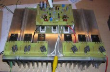
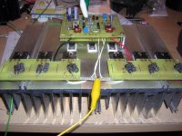
The proto type amp is all up and running just fine on the bench supply so Al you can sleep now....... Can't bias it up all that far... about .112 volts across the emitter resistors. The sink still gets pretty warm though and the amp actually sounds pretty good. I will run it up on normal rail voltage this weekend and post waveform and distortion measurements. If I get real excited I'll try to get the Spectrum analyzer set up and shoot a pic of the distortion spectrum content.
This board set wires up so darned easy that it almost falls together and it looks oh so neat when its done. Yea, I know....
I still got to get some nylon standoffs or make em up.
A couple of photos to get everyone excited😀 !
Mark
Attachments
Damn you guys can keep a conversation goin, I'm without internet for 2 days and already theres so much to read.
My mothers sewingcircle doesn't have a thing on you
Anyway, how about editing in something at the very start of this tread with some basic stuff as recommended trannies, required cooling, capacitance and so on? It seems like theres been a lot of questions about this and it in the last 50-100 replys and it would be much easier to find if someone made a short and very basic collection.
Just an idéa
- Home
- Amplifiers
- Solid State
- Krell KSA 50 PCB