Re: Parts
I had no real problem with getting Dale resistors to match the values... I am using pretty much spot on original rails, so i went "down" a rating for some parts and "up" for others depending on which part it was for....
If you are running ~36vdc rails i'd say choose what you can, but if you want higher voltages pick one that is slightly more resistive....
Aaron
lgreen said:Also many of the part values specified (resistors notably) are not standard 1% values; so is there any problem with getting the closest matching value? If not, which ones are critical and which are not?
I had no real problem with getting Dale resistors to match the values... I am using pretty much spot on original rails, so i went "down" a rating for some parts and "up" for others depending on which part it was for....
If you are running ~36vdc rails i'd say choose what you can, but if you want higher voltages pick one that is slightly more resistive....
Aaron
Re: Parts
I used the closest matching ones myself. I refered to the schematic to see what it's function was and improvised.
Regards
Anthony
lgreen said:Also many of the part values specified (resistors notably) are not standard 1% values; so is there any problem with getting the closest matching value? If not, which ones are critical and which are not?
I used the closest matching ones myself. I refered to the schematic to see what it's function was and improvised.
Regards
Anthony
pinkmouse said:
Well, it's going to be written by one, if that helps! 🙂
Right, a few quick answers for the things I can remember. RE can be anything from 0.1 to 0.68 Ohm, 5W should be plenty. RB, between 0 and 10Ohm.
I'll check the other things later, but I am at work at the moment, so will have to squeeze it in when no-one is looking...
Yes but How do I pick a value? Is there a spreadsheet somewhere like the Aelph-X one available? If I use 0.27R 5 Watt Mills for RE values How will that effecr the choices for the RB values? What is the the suggested values for RV resistors. Surely someone has built, tested and is happy with thier selections on the early boards?
Regards
Anthony
Coulomb said:
Yes but How do I pick a value? Is there a spreadsheet somewhere like the Aelph-X one available? If I use 0.27R 5 Watt Mills for RE values How will that effecr the choices for the RB values? What is the the suggested values for RV resistors. Surely someone has built, tested and is happy with thier selections on the early boards?
Regards
Anthony
Hi Anthony!
How much bias do you plan on running? Having too low a value for RE you will find bias quite "touchy" and possibly hard to get right..... I used 0.68R ones and have had no problems at all setting bias, it's easy to adjust, within a millivolt of what i want!
I never used any RB resistors - the only need for this is to "restrict" the amplifier from going "too far" really, it will limit the output a little - i personally saw no need to have these - if you do want them - anything between 0 and 2.2r specified will do fine.
Aaron
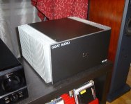
Some pictures of my "setup"......
3rd toroid will be coming when money allows 🙂
But the "big" ones are 172mmx72mm or so 🙂
Aaron
[edit - yes, it's quite messy at the moment - but the wires are "long" because they will have to go into a case sometime.... This is simply the "test" rig (knowing me probably for the next few months!!!) but hopefully going to get it done sometime soon 🙂 It will be custom made casing with a case for each channel 🙂
Now i'm off to buy more parts to complete another 2 lower power version channels 🙂 (for the rear speakers!)]
3rd toroid will be coming when money allows 🙂
But the "big" ones are 172mmx72mm or so 🙂
Aaron
An externally hosted image should be here but it was not working when we last tested it.
An externally hosted image should be here but it was not working when we last tested it.
[edit - yes, it's quite messy at the moment - but the wires are "long" because they will have to go into a case sometime.... This is simply the "test" rig (knowing me probably for the next few months!!!) but hopefully going to get it done sometime soon 🙂 It will be custom made casing with a case for each channel 🙂
Now i'm off to buy more parts to complete another 2 lower power version channels 🙂 (for the rear speakers!)]
NUTTTR said:
Hi Anthony!
How much bias do you plan on running? Having too low a value for RE you will find bias quite "touchy" and possibly hard to get right..... I used 0.68R ones and have had no problems at all setting bias, it's easy to adjust, within a millivolt of what i want!
I never used any RB resistors - the only need for this is to "restrict" the amplifier from going "too far" really, it will limit the output a little - i personally saw no need to have these - if you do want them - anything between 0 and 2.2r specified will do fine.
Aaron
Thanls oh Nutty one, That is helpful, I will be driving a 6 Ohm load with these amps, big 5 driver beauties from Denmark called System Audio 3070. I was thinking of 30 to 50 watts with some Class A/B operation, I understand as the gain increases?
The only spare Transformer I have at the moment is a 750VA 30-0-30 Plitron does this all sound Feasible? One last thing it has to be able to rune stereo in this chassis. The Heat sinks are 13.5x7.5x2.5 there are 38 fins on each side and the base is .375. I made several of these Chassis's, this one is an Aelph-X Stereo version. I got them surplus and have not been able to find a matching profile to figure out the C/W rating. I am guessing around .15C/W
Regards
Anthony
Attachments
power...
Anthony,
With 30-0-30 AC, (41-0-41 DC, loaded) you can easily get >100w RMS into 6ohms, how much of it is class A vs class AB depends on the idle current you dial in. If you have a good thermometer, you can simply increase the standing current until something says uncle.
Based on a lot of folks experience here it's likely the heatsinks for the output that reach their limit first, but if those were big enough it could be the transformer...most people are going with 30c above ambient for the heatsinks, and the plitron website will probably tell you a good temp. to stop at for the transformers...
...0.15c heatsinks will be good for ~200watts total, one of those per channel will allow you ~2.4amps idle current, which is >70w RMS class A into 6 ohms...
IMHO the insertion of Rb was misguided, the original ksa50 didn't need or use them. Unless they are power resistors (like 5w), putting them in will actually increase the likelyhood of a failure when driving very low impedance loads. I (and others) am simply wiring the bases of the output stage together. Basically the highish (>0.5) values of Re enforce excellent sharing. Currently my biggest output stage (KSA???) has 10 of the mj21193/4 (to3) pairs driven by an mjl21193/4 (to247) pair...I'd have done more but I ran out of sockets...
Stuart
Re: power...
That's the spirit!
Got any pics?
Stuart Easson said:...I'd have done more but I ran out of sockets...
That's the spirit!
Got any pics?
soon...
Funny thing is the heatsinks I am using make the output stage look like a pair of small V10 engines, the power cables end up looking like the intake runners and exhaust manifolds...the base wires looking like spark plug wires...
All my calculations suggest that 10 pairs should be more than enough for a 'nice' ordinary 4 ohm resistive load with 90v rails...100v unloaded, but I am a little trepidacious about the full power test...keeping a fire extinguisher close at hand...
I'll probably have to run a 220v cable out from the dryer plug to test the final version...120v not gonna hack it for multiple kW...
Stuart
Re: power...
Thanks Stewie,
1) So I should keep RE to 0.5R or above, but less that 2R
2) Omit RB, do I need to jumper anything? I am using the oiginal 3 Transistor output boards.
I was planning on using the MJL21193/4 devices for ON-Semi, any thoughts
Regards
Anthony
Stuart Easson said:Anthony,
With 30-0-30 AC, (41-0-41 DC, loaded) you can easily get >100w RMS into 6ohms, how much of it is class A vs class AB depends on the idle current you dial in. If you have a good thermometer, you can simply increase the standing current until something says uncle.
Based on a lot of folks experience here it's likely the heatsinks for the output that reach their limit first, but if those were big enough it could be the transformer...most people are going with 30c above ambient for the heatsinks, and the plitron website will probably tell you a good temp. to stop at for the transformers...
...0.15c heatsinks will be good for ~200watts total, one of those per channel will allow you ~2.4amps idle current, which is >70w RMS class A into 6 ohms...
IMHO the insertion of Rb was misguided, the original ksa50 didn't need or use them. Unless they are power resistors (like 5w), putting them in will actually increase the likelyhood of a failure when driving very low impedance loads. I (and others) am simply wiring the bases of the output stage together. Basically the highish (>0.5) values of Re enforce excellent sharing. Currently my biggest output stage (KSA???) has 10 of the mj21193/4 (to3) pairs driven by an mjl21193/4 (to247) pair...I'd have done more but I ran out of sockets...
Stuart
Thanks Stewie,
1) So I should keep RE to 0.5R or above, but less that 2R
2) Omit RB, do I need to jumper anything? I am using the oiginal 3 Transistor output boards.
I was planning on using the MJL21193/4 devices for ON-Semi, any thoughts
Regards
Anthony
Re: soon...
Pure poetry!
Stuart Easson said:Funny thing is the heatsinks I am using make the output stage look like a pair of small V10 engines, the power cables end up looking like the intake runners and exhaust manifolds...the base wires looking like spark plug wires...
Pure poetry!
resistors
If you elect not to use it Rb will simply be a wire jumper, ie a resistor of 0 ohms...
I can't imagine any normal speaker load using 2 ohms for Re, you'll do much better at 0r5 or 0r68. If you need some 0r68/10w I can send them to you, assuming I didn't already...send me an email if you didn't get any...I guess I should add my offer to the wiki...I still have over a thousand...
The MJx21193/4 are most excellent transistors, AFAIK the KSA50 only used the earlier incarnations in the series (mj15003/4) back from when on-semi were a part of motorola. From reading datasheets the newer parts are the same or better in every respect, the only reason 3 (as opposed to 2) were used is because of the packaging change, the to247 is not as capable at dealing with extreme heatcycles as the to3. If you decided to start driving lower impedance loads than the 6 you spoke of you could add another pair for safety...
Stuart
I have to say, both from listening and measuring, the 15003/4 ain't that good, (relatively speaking, they still make a grand amp), compared to the more modern transistors. When I get around to rebuilding/troubleshooting my hard wired monster heatsink, I may well use the 21193/4s, as I have them in T03 cans and it would be a shame to waste all that metalwork...
Re: resistors
Thanks agian, most excellent, now what about those pesky RVI resistors?
Regards
Anthony
Stuart Easson said:If you elect not to use it Rb will simply be a wire jumper, ie a resistor of 0 ohms...
I can't imagine any normal speaker load using 2 ohms for Re, you'll do much better at 0r5 or 0r68. If you need some 0r68/10w I can send them to you, assuming I didn't already...send me an email if you didn't get any...I guess I should add my offer to the wiki...I still have over a thousand...
The MJx21193/4 are most excellent transistors, AFAIK the KSA50 only used the earlier incarnations in the series (mj15003/4) back from when on-semi were a part of motorola. From reading datasheets the newer parts are the same or better in every respect, the only reason 3 (as opposed to 2) were used is because of the packaging change, the to247 is not as capable at dealing with extreme heatcycles as the to3. If you decided to start driving lower impedance loads than the 6 you spoke of you could add another pair for safety...
Stuart
Thanks agian, most excellent, now what about those pesky RVI resistors?
Regards
Anthony
pinkmouse said:Leave all the I/V limiting components out. You don't need it. 😉
Cool, thanks Al, so that would be omit from Main board and output boards? No jumpers required? I installed the speaker protecion circuit, can I still leave the RVi resistors out of that circuit as well?
Regards
Anthony
Al, did you make sometimes short connection at speaker output ? At output of amp, which have toroidal transformer 600 VA, battery of condensers 100 G and any current limit ? Have you imagination, how will look output transistors after this " procedure " ? 
Coulomb said:Cool, thanks Al, so that would be omit from Main board and output boards? No jumpers required?
All the components with designators in the 300 range can be left out. I'm not as familar with that board as I am with my own, but I don't think you need any links.
I installed the speaker protecion circuit, can I still leave the RVi resistors out of that circuit as well?
What speaker protection circuit?
Upupa Epops said:Al, did you make sometimes short connection at speaker output ?
I was very well trained in the pro PA world, I always turn everything off before playing with cables or connectors...🙂
- Home
- Amplifiers
- Solid State
- Krell KSA 50 PCB