Input impedance.
I've ordered a pair of ready built KSA 50 Mk11 clones from ebay after abandoning my Pass amp build.
I see from the Mk11 schematic that there is a 22k resistor which seems to determine the input impedance.
Can I change it to 100k?
(I need 50-100k as my ALPS vol pot is 50k and connected directly to my dual TDA15451 dac's I/V output transformers which need a high Z load.)
Good to be back after a couple of years of abstinence.
I've built a KSA50 clone and I'm wondering if the amp needs a Zobel network. I noticed on the original buy of PCBs a Zobel network was optional. The only reason I ask is that my clone powers a set of ESL57 who's impedance curve is kinda nasty.
I've ordered a pair of ready built KSA 50 Mk11 clones from ebay after abandoning my Pass amp build.
I see from the Mk11 schematic that there is a 22k resistor which seems to determine the input impedance.
Can I change it to 100k?
(I need 50-100k as my ALPS vol pot is 50k and connected directly to my dual TDA15451 dac's I/V output transformers which need a high Z load.)
Good to be back after a couple of years of abstinence.
Which eBay clone did you buy? Ready built too 🙂
And which Pass amp did you pass on?
READY BUILT
I've bought a pair of ready built modules which haven't arrived yet.
One Pair Pure Class A Amp Board Base KRELL KSA50 50W+50W (MJ15024/15025) | eBay
You could build one using bare pcbs for less money but I don't have time.
I also bought a suitable chassis from the same seller but I'm thinking maybe I will need to use some 30mm fans under the fins to keep it cool.
It does come with a Zobel fitted and my Martin Logan Aeons are also a demanding load.
I'm not looking for more than 25-30w into 4r so will be running them on +-35v.
I also bought a tube buffer for my dual differential TDA1541 nos dac.
6J1 Valve Pre-amp Tube PreAmplifier Kit Assembled Board Audio Musical Fidelity | eBay
The Pass amp was an Aleph 5
Aleph 5 Query
I could never get the mosfets to pass equal (or almost equal) current and when I did listen to it, I wasn't that impressed so I cut my losses and binned it. (it was also a ready built kit but I did buy a batch of the mosfets and matched them, to little avail)
Last edited:
Mini Krell KSA50 (25w)
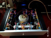
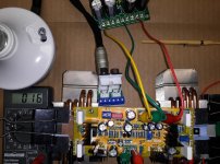
I have at last completed my mini Krell build using the pre assembled modules from ebay and a chassis from the same supplier.
Power suppy is 24v x2 250va, giving +-36.6v on load, with 47000uf reservoir caps.
The heatsinks are running at 50C and the TO3 cans at 70c and 63C for those with a finned heatsink attached. (more on order).
The SQ is a big improvement over the Pioneer AV amp I have been using but I will reserve judgment until they have been burned in for a few days.
I adjusted the standing current preset for 0.7a through each of the 3 pairs of output transistors and the output offset was set to 0v.
Attachments

A bit more work to squeezing the KSA50 into an old Apple G5 case...
 IMG_20201025_211526 by Garf Arf, on Flickr
 IMG_20201101_111734 by Garf Arf, on Flickr
 IMG_20201108_093812 by Garf Arf, on Flickr
 IMG_20201108_093817 by Garf Arf, on Flickr
...a bugger to get in, but the case cost me £25 so I'm not complaining...
IMG_20201025_211526 by Garf Arf, on FlickrIMG_20201101_111734 by Garf Arf, on FlickrIMG_20201108_093812 by Garf Arf, on FlickrIMG_20201108_093817 by Garf Arf, on Flickr...a bugger to get in, but the case cost me £25 so I'm not complaining...

That all fits in quite well.
I built an Aleph 5 into an aluminium flight case, complete with wheels and a telescopic handle. (these proved useful when moving the beast, unfortunately the aluminium wasn't aluminium sheet, it was aluminium foil covered hardboard)
I built an Aleph 5 into an aluminium flight case, complete with wheels and a telescopic handle. (these proved useful when moving the beast, unfortunately the aluminium wasn't aluminium sheet, it was aluminium foil covered hardboard)
Cool
Well done Chilly, 😎
I wouldn't regret £25 either. Compared to that Mercedes at Flickr, that's a real bargain.
I'm still struggling with my DIY chassis.
Well done Chilly, 😎
I wouldn't regret £25 either. Compared to that Mercedes at Flickr, that's a real bargain.
I'm still struggling with my DIY chassis.
Bugger the Merc, the Murvi Morrelo, grey motorhome cost me and arm and a leg...Well done Chilly, 😎
I wouldn't regret £25 either. Compared to that Mercedes at Flickr, that's a real bargain.
I'm still struggling with my DIY chassis.
I find boxing stuff up tricky, but worth the effort compared to wires everywhere 🙂
I missed this post completely. Very smart build indeed. How's the sound quality coming along?I have at last completed my mini Krell build using the pre assembled modules from ebay and a chassis from the same supplier.
Power suppy is 24v x2 250va, giving +-36.6v on load, with 47000uf reservoir caps.
The heatsinks are running at 50C and the TO3 cans at 70c and 63C for those with a finned heatsink attached. (more on order).
The SQ is a big improvement over the Pioneer AV amp I have been using but I will reserve judgment until they have been burned in for a few days.
I adjusted the standing current preset for 0.7a through each of the 3 pairs of output transistors and the output offset was set to 0v.
I thought about using a G5 case as a Class A chassis back a few years myself...just couldn't figure how I was going to get passive heatsinks in it - that is definitely the way to do it...looks cool....
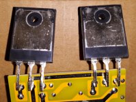
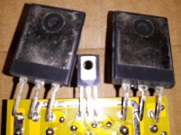
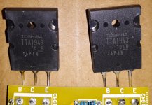
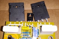
Has anyone else tried the pictured KSA50 board? Before first turn-on any advice? (I will be starting with low rails and large heatsinks. No speaker/load until I check bias, etc.)
Do the included (photographed) TTC5200 and TTA1943 look genuine? I ask since I have run into so many fake power transistors. Maybe I should just check basic function and assembly at minimum operating voltages and then replace the output transistors before going higher?
What is a good minimum operating voltage to test out such a KSA50 as safely as possible for first turn-on?
Attachments

I missed this post completely. Very smart build indeed. How's the sound quality coming along?
I have been pleasantly surprised by the SQ.
Especially by the treble which is much clearer yet strangely, not being more prominent.
Also depth and separation is good and bass tight and controlled.
It shrugs off the tricky load of my ML Aeons.
Overall very smooth and unfatiguing to listen to with no glare or grainy coarseness.
My only gripes are:
Had the heatsink bracket been the same length as the pcb, I wouldn't have had to trim them down with a band saw.
The finned heatsinks were very slightly bowed so the 5mm bolts attaching it to the amp brackets had to be very tight to close the gap (until the heatsink paste was squeezed out).
So far so good.
Last edited:
Has anyone else tried the pictured KSA50 board? Before first turn-on any advice? (I will be starting with low rails and large heatsinks. No speaker/load until I check bias, etc.)
Do the included (photographed) TTC5200 and TTA1943 look genuine? I ask since I have run into so many fake power transistors. Maybe I should just check basic function and assembly at minimum operating voltages and then replace the output transistors before going higher?
What is a good minimum operating voltage to test out such a KSA50 as safely as possible for first turn-on?
I can't comment on that version but with the ones I used, the 10turn preset was adjusted to reduce the standing current to zero so I applied +-36v whilst monitoring the output. The offset was minimal - a few mv so I didn't have to adjust it's preset.
I then increased the current to about .7amp per transistor (2amp total)
Fans would be needed to go higher.
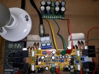
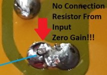
I tried my KSA50 boards with +/-25V (my lowest voltage transformer for a safer first power up) and a 60W Dim Bulb Tester.
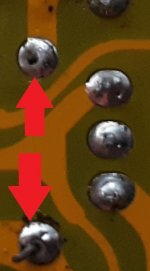
One worked the first time while the other had no output. It took a long time but I found an open in the input section due to a bad solder joint on one side of the first resistor at the input. After resoldering both boards work. So if anyone else gets this version from AliExpress be careful and inspect the soldering with a magnifier and a bright light.
I think this might be the best amplifier I have listened to. My other favorite is the DIY MA-9S2 (Marantz Style).
So is +/-36V the consensus for the optimum supply voltage for 4 Ohm speakers? (I ask since I need to buy an appropriate transformer for this project, and I would like to avoid excessive output stage heating from excessive rail voltages.)
Attachments
- Home
- Amplifiers
- Solid State
- Krell KSA 50 PCB