I am currently busy redoing a layout based on the Pinkmouse boards (as a learning exercise), but with slightly more space for my bigger RND60 Dales (have lots of them), bigger pads for the resistors, the ability to use the bigger Elna Silmic caps for the feedback, and also to use the Japanese transistors in stead of the MPSAs in the FE. I like the fact that the Pinkmouse PCBs has local decoupling on the power rails, which is why I don't want to bother with the eBay PCBs from Jim. When I will be done, heaven alone knows, so don't ask yet. It might take another year, or 2.
Last edited:
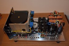
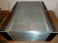
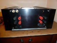
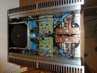
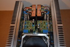
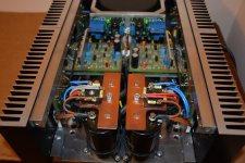
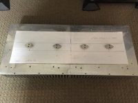
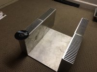
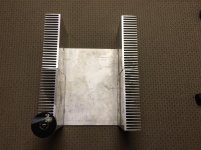
Here are a few pictures I took during the construction of my KSA25. It is dual mono construction with the exception of the "front end"which uses a seperate supply. The boards were modified slightly to enable easier mounting of the driver transistors to their heatsink, this was quite easy to do. Also component values were altered to allow use on 25V rails. The heatsinks are thermaly isolated from the base of the chassis to keep internal temperatures as low as possible. Also fitted are loudspeaker protection boards. All metal work was carried out using hand tools only, with the exception of a piller drill.
I decided on using a lower supply voltage and biasing for 25W for size reasons and passive cooling. Still quite a large and heavy lump.
Still working fine and very easy to listen to.
Alan
I decided on using a lower supply voltage and biasing for 25W for size reasons and passive cooling. Still quite a large and heavy lump.
Still working fine and very easy to listen to.
Alan
Attachments
-
 A89_2084 diy audio.jpg287.6 KB · Views: 839
 -
 P1030642 diy audio.jpg478 KB · Views: 382
 -
 P1030641diy audio.jpg305.4 KB · Views: 455
 -
 P1030640 diy audio.jpg422.9 KB · Views: 796
 -
 A89_2096 diy audio.jpg350.8 KB · Views: 810
 -
 A89_2094 diy audio.jpg367.9 KB · Views: 829
 -
 A89_2090 diy audio.jpg360.5 KB · Views: 833
I like it, very nice.
I would turn the output posts 90* as I always forget to do it myself
Cables always route better horizontally
Regards
David
I would turn the output posts 90* as I always forget to do it myself
Cables always route better horizontally
Regards
David
I am currently busy redoing a layout based on the Pinkmouse boards (as a learning exercise), but with slightly more space for my bigger RND60 Dales (have lots of them), bigger pads for the resistors, the ability to use the bigger Elna Silmic caps for the feedback, and also to use the Japanese transistors in stead of the MPSAs in the FE. I like the fact that the Pinkmouse PCBs has local decoupling on the power rails, which is why I don't want to bother with the eBay PCBs from Jim. When I will be done, heaven alone knows, so don't ask yet. It might take another year, or 2.
Hey henryve, this would be awesome, i like more japanese transistors, mpsa are relatively expensive in my country.
would be a nice contribution if you do it.
regards wolfintosh
After a loooong hiatus, i'm back, and need a project...
Thoughts on my ksa50 build:
-30-0-30 1000VA x1
-CCLCCLCCCC - maybe CCLCCLCCRCC to drop a few volts (yes, thats 16 caps)
-biased as high as heatsinks can safely handle
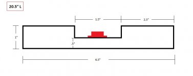
-Heatsinks are 10"h x 11.75"w x 3.25"high, .5" base - (2 per/ch)
Thoughts on my ksa50 build:
-30-0-30 1000VA x1
-CCLCCLCCCC - maybe CCLCCLCCRCC to drop a few volts (yes, thats 16 caps)
-biased as high as heatsinks can safely handle
-Heatsinks are 10"h x 11.75"w x 3.25"high, .5" base - (2 per/ch)
Attachments
OR
If i'm feeling lazy, use 1 of these per channel. Nice thing about these is that you can mount one transistor per quadrant without mica, as each section is electrically isolated.
If i'm feeling lazy, use 1 of these per channel. Nice thing about these is that you can mount one transistor per quadrant without mica, as each section is electrically isolated.
Attachments
Last edited:
guys, whats the correct value for R124.
according to the original schematic its 47kΩ, i previously used 820Ω and the amp worked, not correctly biased in the scope it looked like class b operation and distorted a lot under low volumes, after replacing his resistor to 47k i didn't manage to get it working with load, it makes some strange noises, any thoughts?
also i simulated de original schematic i multis and worked nice if some one is interested, also in making a clone board using original components.
Regards wolf
Hello All. I have been dipping my toe in the this hobby as of late and have my first attempt based on the "cheap" Ebay KSA50 assembled board. I'm not sure how close it even resembles a Krell KSA50.?.
Here is the short thread that I have been chatting on: http://www.diyaudio.com/forums/solid-state/190411-ebay-ksa50-needs-2-voltages.html
I have to say it seems to works quite well and is dead quite at idle (600ma bias).
Fun so far. Not sure If I want to build this one a house or experiment with different designs before I commit to all that aluminium.
I have never heard a real Krell so have nothing to compare to. Also, at the price of these boards (< $40 USD complete) many have questioned if the 1943/5200's are authentic. I have no idea how to truly know. Based on the threads and sites I have researched they look original. I also have 7 sets of them sitting on my desk that I pulled from a dead Arcam AVR250 and they look very similar.
Trying to find out input sensitivity for these boards. If anyone is up to translating the Chinese from the attached schematic I would appreciate it.
Thanks
well the provided schematic looks quite similar to jans schematic, its only different in some dc decoupling capacitors and i only hesitate in the gain resistors and offset the rest seems excellent, does that board worth it?
hey guys, thanks for your enormous support, its been quite an awesome journey for me, as my first amp project, lots of learning, finally i got 1 channel working perfectly, its sounds like heaven to me, my next step its to use the mje15030 in the bias instead of c3955 and c 2238 and 2sca968 like the original.
my las doubt is biasing, the one I've tested has .22 emiter resistors, im planning to use .56 resistors, my doubt remains thad the amp its drawing 1 amp per rail in my current bus setting and with 8 ohm load, it peaks at 1.5 per rail with signal and the current supply voltage is 31v, with this can i achieve at least 50wpc at class A
im planning to run it with +/-40 v with jan boards, o DIY them, but after this ill sen some for production, i founded on the web the gerber files if someone is interested in some boards.
regards wolf
What speaker impedance?....................can i achieve at least 50wpc at class A.................
ClassA is a current limit. That current allows power to be dissipated at the load.
Power = Ipk² * Rload / 2
OR
If i'm feeling lazy, use 1 of these per channel. Nice thing about these is that you can mount one transistor per quadrant without mica, as each section is electrically isolated.
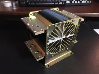
Hello MEGA_amp
I just starting my KSA100 build and would like to know where you purchased the fan cooled heatsink?
Thx
Last edited:
Hi Bonanza, I have a pair of heat sink tunnels very similar. Also brand new Papst fans to suit them. Also some large passive cooled heat sinks if you don't want to go the forced air route. If you are interested ( or anyone else ) send PM and I will send pictures etc.
Alan
Alan
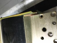
Transistor?
I started a few days before the construction dl Krell ksa 50 and I met the first problem: I can not find the transistor 2sc2240 and 2SA970 Thoshiba original.I'like riceveire guidance on where I can buy them. For all other transistors choose those indicated on the schematic Delta Audio Denmark Kre Ksa 50 dates 13.02.2005 Rev.1.5.
I started a few days before the construction dl Krell ksa 50 and I met the first problem: I can not find the transistor 2sc2240 and 2SA970 Thoshiba original.I'like riceveire guidance on where I can buy them. For all other transistors choose those indicated on the schematic Delta Audio Denmark Kre Ksa 50 dates 13.02.2005 Rev.1.5.
- Home
- Amplifiers
- Solid State
- Krell KSA 50 PCB