This chassis do not have enough heatsink for the KSA50 project if you want to run it with full class A to 50W. That is the chassis for a KS50S which used sustained plateau bias concept, which drastically lowered the quiescent current when the amplifier is idling.
Last edited:
This chassis do not have enough heatsink for the KSA50 project if you want to run it with full class A to 50W. That is the chassis for a KS50S which used sustained plateau bias concept, which drastically lowered the quiescent current when the amplifier is idling.
This is true - maybe monblocks could work with those?
My KSA-50 Clone pulls around 700W from wall, and all but 100W (stereo) go to heatsinks. I have a real KSA300 Chassis that I am putting another KSA-50 Clone into....that has a lot of sinking...
It will probably work for monoblocks, but then you will have another problem to solve, that being that you will need to have long leads from the driver board to the outputs. That just opens you up for problems with oscillations etc. Still a usable chassis though. Just replace the heatsinks with something similar to what the KSA80 used. And save those heatsinks for something else.
My KSA50 clone is still running strong and sees daily use. My chassis is 520mm deep, 200mm tall, with sinks running both sides for the full length. The sinks have 70mm fins and a 16mm base, and they get quite hot in summer. I guess just shy of 60°C. Mine are biased at around 1.95A per channel.
My KSA50 clone is still running strong and sees daily use. My chassis is 520mm deep, 200mm tall, with sinks running both sides for the full length. The sinks have 70mm fins and a 16mm base, and they get quite hot in summer. I guess just shy of 60°C. Mine are biased at around 1.95A per channel.
Last edited:
I will ad that the original KSA-50 clone is still operating just fine from when this thread started. That was about March 2004 give or take.... I still have extra version 1 prototype boards and some Version 2 gold plated boards left! I should think about recapping that prototype pretty soon I guess.
Mark
Mark
Yes, big beer cans are getting rare. I myself will want to redo my PSU soon once my tube amp is up and running. I will probably replace the caps with an array of smaller caps. I have some cheap Indian made caps in there at the moment. Spragues were already out of budget when I did mine originally.
I don't think so.This is true - maybe monblocks could work with those?
My KSA-50 Clone pulls around 700W from wall, and all but 100W (stereo) go to heatsinks. I have a real KSA300 Chassis that I am putting another KSA-50 Clone into....that has a lot of sinking...
The output bias is ~1.9A per channel.
The KSA50 supply rails are ~±35Vdc.
That equates to 133W per channel. Allow another 5% for driving the front and and 5% for losses in the PSU and cabling and you arrive at a total dissipation of ~300W (not 700W). That is why a 1kVA transformer works continuously with that stereo load.
All that power is dissipated inside the chassis. The air inside has to get rid of some but most is dissipated by the fan blown heatsinks.
Even a KSA 100 (monoblock) does not dissipate 700W after being fed from it's 1kVA transformer. It too is about 300W total dissipation. The pair of monoblocks would come to a total dissipation of around 600W fed from two 1kVA transformers.
Last edited:
I don't think so.
The output bias is ~1.9A per channel.
The KSA50 supply rails are ~±35Vdc.
That equates to 133W per channel. Allow another 5% for driving the front and and 5% for losses in the PSU and cabling and you arrive at a total dissipation of ~300W (not 700W). That is why a 1kVA transformer works continuously with that stereo load.
All that power is dissipated inside the chassis. The air inside has to get rid of some but most is dissipated by the fan blown heatsinks.
Even a KSA 100 (monoblock) does not dissipate 700W after being fed from it's 1kVA transformer. It too is about 300W total dissipation. The pair of monoblocks would come to a total dissipation of around 600W fed from two 1kVA transformers.
Hey Andrew, whats the best way to bias the amp, my heatsink its massive around 5kg of aluminum with 42v rails, is it ok? or 35 v its better?
AndrewT:
My KSA-50 is not quite setup / biased like a true KSA-50.
Rails are +/-38VDC
Emitter resistor is .64 ohm
Voltage across emiiter resistor 640mv
3 pairs 2SC5200/2SA1943
From wall outlet
612 VA
480 watts
I was incorrect - not 700 watts, but 612 VA / 480 watts
So, what do I have in class A? My guess is 72 wpc @4 ohm
640mVre across a 0r64 emitter resistor is 1A of bias current.Rails are +/-38VDC
Emitter resistor is .64 ohm
Voltage across emiiter resistor 640mv
3 pairs 2SC5200/2SA1943
.................what do I have in class A? My guess is 72 wpc @4 ohm
A 3pair output stage will have a total bias of 3A
A push pull output stage will turn off one side when output current reaches twice the bias current, i.e. 6A
The maximum ClassA output is Ipk²*R/2 = 6²*4/2 = 72W into 4r0.
Your answer is correct.
Everyone else, the arithmetic is straight forward, no magic required.
The output stage dissipation is: total rail to rail supply voltage times the bias current, i.e. 38+38V * 3A = 228WRails are +/-38VDC
..................From wall outlet
612 VA
480 watts
I was incorrect - not 700 watts, but 612 VA / 480 watts
The dissipation of the PSU and front end and drivers could be around 10% of that i.e. ~20W.
Total loading on the transformer ~250W
Typical recommendations for a ClassA power amplifier transformer is roughly 6times to 10times the maximum ClassA output as the VA.
i.e 72W gives a required VA of 432VA to 720VA, your 612VA fits within that recommendation.
Last edited:
Hey Andrew, whats the best way to bias the amp, my heatsink its massive around 5kg of aluminum with 42v rails, is it ok? or 35 v its better?
I will butt in if Andrew don't mind.
1) It is really not important how heavy your heatsink is, although it is one parameter which may help. What is more important is the rating of the heatsink. This is usually dependant on the profile, mass and material of the heatsink etc. It is also important how you mount the heatsink, and how efficient the thermal coupling is between your output transistors and the heatsink. Also bear in mind that with this amp the ambient temperature (Ta) plays an enormous role on what your bias would be. For example, our winter Ta average is about 15°C, while our summer Ta average is about 33°C. That is a difference of 18°C. Do the same for your environment, given what your heatsink rating is, to decide on what you can use for a bias level. Many people have a winter and summer bias level.
2) 42V should be fine still. No need to drop down I believe. My rails are on 38.8V under load, and have been biased to 1.95A. My Re = 0R5. And the amp have been reliable for the past 2 years, even on days where our Ta were 42°C. Make sure that you bias the amp with no input, and no safety lamp on the supply. Also check the bias again after the amp have reached it's thermal equilibrium.
Regards
Henry
Last edited:
AndrewT:
My KSA-50 is not quite setup / biased like a true KSA-50.
Rails are +/-38VDC
Emitter resistor is .64 ohm
Voltage across emiiter resistor 640mv
3 pairs 2SC5200/2SA1943
From wall outlet
612 VA
480 watts
I was incorrect - not 700 watts, but 612 VA / 480 watts
So, what do I have in class A? My guess is 72 wpc @4 ohm
awesome john, im using the same transistors for output but with .22 resistors as the posted schematic, would it be ok to get around 640mv for 50w class A or more power
thanks and regars wolf
Wolf:
For three pairs (like mine), you will not need 640mv across your .22 ohm emitter resistors, just 220mv to get the 1A/Device.
As andrew indicated, 50W will be 1.9A, not the 3A total I have, so bias should be around 210mv across your .22 emitter resistor for 1.9A (50W).
Someone check my bad math!!
For three pairs (like mine), you will not need 640mv across your .22 ohm emitter resistors, just 220mv to get the 1A/Device.
As andrew indicated, 50W will be 1.9A, not the 3A total I have, so bias should be around 210mv across your .22 emitter resistor for 1.9A (50W).
Someone check my bad math!!
OK, I am wrong again...
"As andrew indicated, 50W will be 1.9A" - I think this is correct for 2 output pairs into 8 ohm.
"so bias should be around 210mv across your .22 emitter resistor for 1.9A (50W)." - for your amp, this should read 183mv across .22 ohm emitter resistor for 3 Pairs for 50W Class A in 4 ohm.
Of course, I could still have it wrong 😱
Last edited:
OK, I am wrong again...
"As andrew indicated, 50W will be 1.9A" - I think this is correct for 2 output pairs into 8 ohm.
"so bias should be around 210mv across your .22 emitter resistor for 1.9A (50W)." - for your amp, this should read 183mv across .22 ohm emitter resistor for 3 Pairs for 50W Class A in 4 ohm.
Of course, I could still have it wrong 😱
thanks john so it would be for 3 output pairs?
and also i only want high bias setting do i need to solder high bias and low bias pots?
thanks and regards wolf
Wolf - High / Low Bias pots? Don't understand - I only have one set of pots - one pot for DC offset, one for Bias. Per channel
Your heatsink will determine what heat dissipation you can afford. From that you can decide your final bias point, which will tell you output power.
I have quite a bit of room in my sinks and power supply, so I went after 1A per device.
If you have three pairs output devices and .22 ohm resistors, start your bias point low and slowly work it up until your heatsinks are hot enough. Once you get to 185mv, (again, assuming you have 3 pairs output devices and 4 ohm speakers), you should be at 50 Watts Class A at 4 Ohm.
Nelson Pass has the Heat sink temperature "method" - basically when it is too painful to have your hand on the sink for more than 5 seconds - this equates roughly to 140F. You should not be hotter than that as you risk burning up your output transistors. Of course you can always just take a temperature measurement...
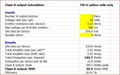
I got an email after a few years from DIYAudio... brings back memories ... I think you need my old excel spreadsheet to calculate Class-A power. Wolfintosh, here is your result to get 50 w into 4 ohms.
Just re-do the math for 8 ohms and it comes to 130mV across each ER gives u 50 watts rms class A.
EDIT
Not sure how I can attach an excel file it to this reply... I selected it, but does not show up here... any ideas?
Just re-do the math for 8 ohms and it comes to 130mV across each ER gives u 50 watts rms class A.
EDIT
Not sure how I can attach an excel file it to this reply... I selected it, but does not show up here... any ideas?
Attachments
Last edited:
- Home
- Amplifiers
- Solid State
- Krell KSA 50 PCB