1 :
a production KSA50 is biased to 50 Watts in 8 ohm, clips at around 75W, it's not good to make a Class AB power amplifier of the KSA50.
It is far less difficult to have a decent sounding class A amplifier than it is to design a good Class AB one.
Build something else if you desire Class AB, money better spent.
2:
For 50W/8 ; 0.6A per device for a 6-device output stage, 0.9A for 4 devices.
3:The factory KSA50 has a 400VA per channel, if you bias it to 50W/8 you'll need at least 250VA/ch.
4: duuh
5+6:nope, too difficult.
You'd have to hand trace each and every device, provided you have a good transistor tracer.
You'd end up having to buy thousands of devices, but picking the best matching hFe pairs you have with a DMM is free of charge.
My heat sink enough to ksa50?
First Thanks evrybody helping me!
And I want to confirm that my heat sink enough to ksa52 or not?
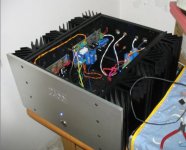
The heat sink show following picture:
image 1 is 45kg ,i using for PASS ALEHP5(550mA per driver *3drivers)
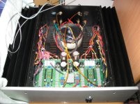
image 2 is 15kg, i using for a small class A amp. 500mA*2drivers.
which would enough better to use for ksa50?
I have another idea that use fan to heat output, it can make heat sink smaller?😀 ,this better idea?
I would to consult that which is better between PASS ALEPH5 and ksa50£¿
First Thanks evrybody helping me!
And I want to confirm that my heat sink enough to ksa52 or not?
The heat sink show following picture:
image 1 is 45kg ,i using for PASS ALEHP5(550mA per driver *3drivers)
image 2 is 15kg, i using for a small class A amp. 500mA*2drivers.
which would enough better to use for ksa50?
I have another idea that use fan to heat output, it can make heat sink smaller?😀 ,this better idea?
I would to consult that which is better between PASS ALEPH5 and ksa50£¿
Attachments
Aleph 5...
To add to Andrews comments:
If the Amp you show in the first picture really is an Aleph5 clone, ie 2 x 60w RMS, then the heatsinks, transformer, rectifier and caps are a good fit for a KSA50.
I've built and swapped between a pair of otherwise very similar amps. They have quite different voices, and depending on your speakers etc, if you like one you may not like the other.
symmetrical output? Not 100% sure I know what you mean. By default it is not a bridged amp. The output of the KSA50 comprises 2 or more complementary pairs of BJTs ie PNP/NPN. I'm sure the circuit could be modified to be quasi- complementary, but AFAIK no-one has tried it.
HTH
Stuart
The MJE15032/33 can instead of MPSA42/92?
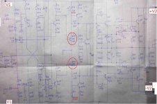
I see some SCH of chinese useing that i show bellow the image 1.
The MJE15032/15033 instead of MPSA42/92(Q103/104),and without change any value of resistance.
You have somebody try to it, it is true? It is feasible??
Because I easy to buy MJE15032/15033,but difficulty to buy MPSA42/92,
1. So if MJE15032/33 can instead of MPSA42/92, I want to use the MJE15032/33.
(But I don't know it is instead of MPSA42/92 feasible???)
. Follow the image 1:
I label the supply voltage on the image 1 ,(the voltage of pre_amplifier and the voltage of power_amplifier )
2. How many volts of that two supply voltage,(i see somebody use +/-48v,)
3. The two voltage supply alone or supply togerther??
😀
Attachments
Zen,
download the datasheets for these transistors.
Don't bother reading them just look at the picture of the devices.
Are they different?
Could they be equivalent?
Any five year could answer this!
download the datasheets for these transistors.
Don't bother reading them just look at the picture of the devices.
Are they different?
Could they be equivalent?
Any five year could answer this!
Zeng,
a Beta-enhanced-Vas is nice, but done with two 50W MJE devices is as unwise as it gets.
If you need anything for the KSA50 you can't get overthere, just mail me and i'll send some junk to China.
a Beta-enhanced-Vas is nice, but done with two 50W MJE devices is as unwise as it gets.
If you need anything for the KSA50 you can't get overthere, just mail me and i'll send some junk to China.
jacco vermeulen said:.... junk to China.
Jacco.... thats two words you don't wanna use so close to each other... it opens up so many dimensions...

i thanks everyone helped me
i come here for consult everyone modest ,sincere,friendly.

I have a simple though,and i am a simple man.😀
I want to speak to everyone in genty way although my English poor.
and i am a young people ,have a young thining.
Everybody have be a proficient.
so if my way of speak or my word out of the way,don't fun of me, and forget me.🙁
i believe that all the man created by god is friendly
i don't know all the mean what "junk to china",
I think the friend Jacco mean that he want to help me, so I very thanks for him.🙂 .
😕
i come here for consult everyone modest ,sincere,friendly.
I have a simple though,and i am a simple man.😀
I want to speak to everyone in genty way although my English poor.
and i am a young people ,have a young thining.
Everybody have be a proficient.
so if my way of speak or my word out of the way,don't fun of me, and forget me.🙁
i believe that all the man created by god is friendly
i don't know all the mean what "junk to china",
I think the friend Jacco mean that he want to help me, so I very thanks for him.🙂 .
😕

Jacco:
thanks.
tell the true ,
some value of resistance,is difficulty to buy,
some transistor are difficulty to buy because i need too few.
i am sorry to you for my misunderstanding.😉
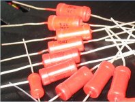
And I have some resisitance look beautiful, can use in ksa50?
some vlaue to fit the ksa50.
thanks.
tell the true ,
some value of resistance,is difficulty to buy,
some transistor are difficulty to buy because i need too few.
i am sorry to you for my misunderstanding.😉
And I have some resisitance look beautiful, can use in ksa50?
some vlaue to fit the ksa50.
Attachments
Hi there guys.
It seems that I have missed the boat on this one looking at all the posts and the dates when most of the activity happened.
Are there any Main and Driver PCBs available from Bob or anyone else?
I had a look at both the KSA 50 and KSA 100 II wikis, and don't seem to get any clear answer about it there, although the GB for the 100's PCBs are closed.
Would you recommend the 50. I have been away from electronics for about 15 years. Since then the internet happened, which makes it much easier than before to get hold of parts.
Any recommendations, advice gladly accepted.
Henry
henryve said:Hi there guys.
It seems that I have missed the boat on this one looking at all the posts and the dates when most of the activity happened.
Are there any Main and Driver PCBs available from Bob or anyone else?
I had a look at both the KSA 50 and KSA 100 II wikis, and don't seem to get any clear answer about it there, although the GB for the 100's PCBs are closed.
Would you recommend the 50. I have been away from electronics for about 15 years. Since then the internet happened, which makes it much easier than before to get hold of parts.
Any recommendations, advice gladly accepted.
Henry
Henry,
There are still KSA50 boards available. Send me a PM or mail bobgroger_at_hotmail_dot_com for details. KSA100 boards are gone but a second GB could happen if someone wants to take charge. The KSA50 had a lot of interest, and about 150 boards were sold. No idea how many were completed. Mine was completed to the "parts on a board with clip leads everywhere" stage. I have lately been collecting metal working tools so an enclosure is in the near future. Either amp makes a great room heater for the winter.
Bob G.
😀 Thanks Bob.
I will send mail re the KSA 50 PCBs. Seems wiser to start of with this one since it is cheaper to get done than the KSA 100.
If I make a success of it then I will look at the 100, although I would jump on a new GB if one happens.
Cheers
I will send mail re the KSA 50 PCBs. Seems wiser to start of with this one since it is cheaper to get done than the KSA 100.
If I make a success of it then I will look at the 100, although I would jump on a new GB if one happens.
Cheers
Just a simple question.
Is there any point in running with more than 3 pairs of output transistors if it is going into a 6 ohm load?
I am thinking of using a transformer with 30-0-30 secondaries, although it might be 35-0-35 if I feel adventurous.
I plan to do 2 monoblocks.
Is there any point in running with more than 3 pairs of output transistors if it is going into a 6 ohm load?
I am thinking of using a transformer with 30-0-30 secondaries, although it might be 35-0-35 if I feel adventurous.
I plan to do 2 monoblocks.
I would run an SOAR on the proposed devices and the proposed load before coming to a decision like that.
Please explain what an SOAR entails.
Can it be done mathematically, or do I need the actual devices in a lab set up?
Will it influence my transformer decision?
I am currently planning on using MJL21193/4 output transistors, although I might be swayed on that decision.
I am not really that much interested in exactly duplicating the 'Krell' sound, since it is too subjective, and my current sources (Rega 3 Planar + Rega Elys Cartridge, Rotel RCD 955BX CD) won't be able to reveal such nuances in any case.
I am just looking for a solid, simple, proven class A implementation, and the KSA 50 suits that. If I can use better output transistors, I will use it.
Henry
look for Bensen's spreadsheet or try a similar calculation from David Feather, or Email me for a BJT version.
Someone (Janneman?) recently posted a link to his spreadsheet that does a similar job.
BTW,
I have checked the SOAR for 3pair 2sa1943 and find that 140W into 6ohms @ 60degree phase angle with Tcmax<=75degC is just on the 100mS limit using 35Vac transformer and +-45mF smoothing. But this PSU voltage will require much higher dissipation heatsinks than the KSA50 had. More like the doubled dissipation of the KSA100.
A 30Vac transformer allows 140W into 40hm for the same conditions, but with a greater safety margin between load line and the 100mS SOAR.
Higher power/SOAR devices will allow higher supply voltages and/or lower load impedances eg the 230W MJL4281/4301
- Home
- Amplifiers
- Solid State
- Krell KSA 50 PCB