Umm, ahh, well this is a bit embarrassing...R501 - R503 and R507 - R509 tuned out to be 2.2k ohm, not 2.2 ohm.
I will correct asap...
Sorry all.
I will correct asap...
Sorry all.
Well done John. Anyone who says they haven't done exactly the same thing at some point is lying, we've all been there! 🙂
Bingo. We have liftoff...
Sound is quite nice. Need to button up the two channels to the monster power supply.
A tiny bit of hum, but not worth messing with.
Pics are forthcoming...
Sound is quite nice. Need to button up the two channels to the monster power supply.
A tiny bit of hum, but not worth messing with.
Pics are forthcoming...
You can get it completely silent. Just pay some attention to lead dress, which is I suspect is your problem.
I will address that - Thanks.
One thing I did notice is that I could drop the DC Offset to nearly 0mv (+/- 15mv swings) on one channel, but the other channel was at best 250mv before the pot was maxed out...
One thing I did notice is that I could drop the DC Offset to nearly 0mv (+/- 15mv swings) on one channel, but the other channel was at best 250mv before the pot was maxed out...
It's amazing how a couple new batties in a voltmeter can fix things. I wish I had thought of that a few days ago, as I spent all that time trying to figure out the 250mv DC offset on one of the channels. Luckily didn't remove or modify any components on the boards...
DC Offset is now 35mv and 12mv at 630mv bias across .649 ohm resistors at heatsink temp of 133F (57C)...
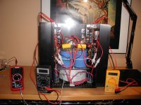
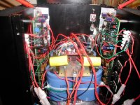
Aside from wiring up a switch and putting installing the 70C thermostatic switch, I am done. A pic below of the monstrosity.
Those heatsinks are 14" high and 10" wide with 2 1/2" long fins. 1240VA dual 29V-0-29V toroid, 4.7uF 400V poly bypass caps, 1-2 second soft start for the power supply...
Only two of the four sinks are connected to the output devices - I may add a couple more device pairs on one of the two unused sinks to lower overall temp on those two sinks currently connected...
Sounds great! Tiny bit of hum, but will most likely fix that when I finalize wiring...
DC Offset is now 35mv and 12mv at 630mv bias across .649 ohm resistors at heatsink temp of 133F (57C)...
Aside from wiring up a switch and putting installing the 70C thermostatic switch, I am done. A pic below of the monstrosity.
Those heatsinks are 14" high and 10" wide with 2 1/2" long fins. 1240VA dual 29V-0-29V toroid, 4.7uF 400V poly bypass caps, 1-2 second soft start for the power supply...
Only two of the four sinks are connected to the output devices - I may add a couple more device pairs on one of the two unused sinks to lower overall temp on those two sinks currently connected...
Sounds great! Tiny bit of hum, but will most likely fix that when I finalize wiring...
Attachments
I have buttoned up the chassis up and kept the bias at 630mv. Gives me just under 1 Amp/device.
I have all four rail leads fused at 3A slo blo. Since enclosing the chassis, one of the rails (positive rail on right channel) blows quite intermittently after about 5 minutes of operation... thinking 3A slo blo a bit too close to the edge.
I think I need to raise this fuse rating.
The mains fuse is 6A slo blo...seems to work fine...
I raised the 3A to 4A slo blo for all four rail connections. I also noticed a loose negative rail wire at caps - tightened it and all good again.
I want to continue operation for a little while with test speakers before I connect to the maggies...
I want to continue operation for a little while with test speakers before I connect to the maggies...
Hi,
for 4ohm speakers I would recommend F5A fuses for the supply rails after the main smoothing caps.
for 4ohm speakers I would recommend F5A fuses for the supply rails after the main smoothing caps.
My speakers are 4ohm. I will change the fuses to 5A slo blo - The mains fuse is 6A Slo Blo and working fine so far...
So I wasn't crazy - the DC offset issue is still there...
I am able to knock down the DC offset to near 0 on the Left channel, but still have 400mv minimum on the right - the pot is min'ned out all the way to 0 ohm. I re-soldered all the connections and checked few resistors and capacitors...all looks OK
Also, when I turn the amp off, the output voltage immediately ramps up to 15VDC before starting to drop on that same channel...
Any words of wisdom out there?
I have the bias on both channels ramped up to 630mv on .649 ohm resistors. 40VDC rails.
Once again...if I just follow the directions...I did not have the signal ground attached to the Starground.
After it was connected I was back in business. Able to adjust both channels to zero Offset..
More about the sound quality later...
After it was connected I was back in business. Able to adjust both channels to zero Offset..
More about the sound quality later...
Yes, much much better. Now the DC Offset is withing 25mv both channels. Sound quality seems to have improved a bit too. Sounds very nice!!
One thing I noticed in correctly connecting the signal ground to the PS Star Ground is that the heat sinks run cooler - went from 55C to 40C.
Is this explainable?
One thing I noticed in correctly connecting the signal ground to the PS Star Ground is that the heat sinks run cooler - went from 55C to 40C.
Is this explainable?

Just out of curiosity, what did these amps cost you guys to build in terms of the small electrical components? So not including chassis, power toroid, and main power caps. Just the actual amplifier part.
Thanks,
Austin
Thanks,
Austin
I did a parts GB for both PCB's but I don't recall the cost...
Maybe I can go back and see what I received in Paypal payments.
The Wiki might have it too.
Maybe I can go back and see what I received in Paypal payments.
The Wiki might have it too.
Ultimately the small components of the majority of amps may only account for say 20 to 30% of the cost....
- Home
- Amplifiers
- Solid State
- Krell KSA 50 PCB