Boards for KSA 50
Hello everyone !
I am interestet in buying 4 boards for the KSA 50 - anybody that have bought to many / knows where some can be bought.
I have 2 assembled Zen4 boards, and two assembled A30 boards, complete with all transistors ect. that can be included in a deal.....
Cheers !
Hans
Hello everyone !
I am interestet in buying 4 boards for the KSA 50 - anybody that have bought to many / knows where some can be bought.
I have 2 assembled Zen4 boards, and two assembled A30 boards, complete with all transistors ect. that can be included in a deal.....
Cheers !
Hans
Take up to much space
AndrewT:
i have been using Alu angels for a long time but the benefit to this design is more space inside the chassis for transformer, big computer caps, 4 (MJE15032/33) driver boards to the 8 pair of MJ15003/4, soft start delay board, VU meters, PSU for balanced inputs besides a very efficient heat transfer construction. I should design output device PCBs myself and I would like to post pictures here when this has been done.
Regards 😎
AndrewT:
acenovelty:Hi Flod,
try a 50 by 50 by 6mm aluminium angle.
nice design acenovelty.Something like this.
i have been using Alu angels for a long time but the benefit to this design is more space inside the chassis for transformer, big computer caps, 4 (MJE15032/33) driver boards to the 8 pair of MJ15003/4, soft start delay board, VU meters, PSU for balanced inputs besides a very efficient heat transfer construction. I should design output device PCBs myself and I would like to post pictures here when this has been done.
Regards 😎
Can anyone please tell me if q107 - q108 on the mainboard needs heatzink, eventually link me to a reply that explains it.
That would be a great help, i have now modified my chassis so that i can mount 4 pieces of 80 mm fans - one fore a duct and the other one fore heatzink fins,fore each side, that has to be good enough i'm able to start a tsunami with those fans (well.. a very very small one, could possibly move a piece of paper at least 1 meter..)
After modifying i'm able to mount the driverbords vertical on the side of the heatsinks together with the outputboards , so that Q109,Q111,q110 is fastened to it near the outputs, that's good.
I have searched, but i am still a little confused wether q107 and q108 needs separate heatzinks.
I can't wait to get the Krell finished and listen to it so please help me, i'm so close to now.....
KSA 50 PCB wanted...
Hello everybody - is there some kind of GB going on, or mabye one just finished, with someone having some spare pcb's ? I am very interested in PCBs for the KSA 50.
Just another question - is the KSA 50 designed to double its power when the load is halved, just like other krells ? Judging from the BIAS at 2 amps i guess not ??
Thanks !
Hans
hmm...power doubles...
The original Krells had great current capacity but not in class A, by the time the KSA50 was driving a 4 ohm load to more than ~25w it was no longer a class A amp, and with 2 ohms the class A level had dropped to ~12.5w...on the other hand the maximum classB output into 8ohms was ~70w, into 4 ohms about 130, and so on. Not quite twice as much, but very nearly.
The idle current or bias determines the amount of class A power the amp can deliver before either half of the output stage is turned off, in this case it's ~1.9A to give the 50w RMS...the same as the original KSA50. The KSA100 had idle current increased to ~2.6A.
The ultimate power the amp can deliver into any particular load after the class A limit is exceeded depends on the voltage rails, number of outputs, size of the heatsinks and the size of the power supply, all of which probably depend on the size of your bank balance...
HTH
Stuart
Krell PCB's
Buhl,
Mark Gulbrandsen did the last board group buy. I don't know if there are any left, but I sent my $$ last year and have seen no boards yet
Bob G.
Buhl,
Mark Gulbrandsen did the last board group buy. I don't know if there are any left, but I sent my $$ last year and have seen no boards yet
Bob G.
Hi,
Perhaps this is a very basic question, but I was wondering where I should connect the input ground; should it be on the main board, or should it go straight to the star ground?
Thanks.
Paul
Perhaps this is a very basic question, but I was wondering where I should connect the input ground; should it be on the main board, or should it go straight to the star ground?
Thanks.
Paul
Hi Joey,
there's a pin location labelled right next to the signal input (below 1 of input1).
There are two other adjacent ground pins.
The next one (below N of input1) goes to central star ground and the third one (way out to the left), next to -V, goes to power ground.
Hope this is clearly explained.
Edit:- I never asked which board you have, I am referring above to the later Pinkmouse 2005 PCB
Repost to Mark
Mark is out on work assignment in eastern Wyoming. He read Bob's note and wrote this to me for posting:
"I lost a page of board purchasers so he musta been on
there. Can you post a message to the effect that it
will be taken care of as soon as I get back and also
for any others that have not received boards to please
e-mail me through the site and let me know. I will
make a seperate file to put those into so they don't
get lost..... I think there was 5 or 6 names on that
list.
Thanks!"
So take note and let Mark know later this week, it may be a week from next Monday when he can reply online.
Lyndon
Hi Andrew,
I am using the Pinkmouse boards.
I attached a picture with the way I set the grounds, but it seems that I am completely confused, since I only have a star ground for everything. Should the power ground (the one from the 2 bridges?) be separate from the star ground?
Thanks.
Paul
I am using the Pinkmouse boards.
I attached a picture with the way I set the grounds, but it seems that I am completely confused, since I only have a star ground for everything. Should the power ground (the one from the 2 bridges?) be separate from the star ground?
Thanks.
Paul
Attachments
gooday said:So long thread,very good!thanks all of diyer.
Is that "so long" thread (goodbye)?
or maybe "the thread is sooooo long"
Either way, you may be interested in a total to-date. Here are the totals- those of individuals with over 10 posts on this thread.
Total Posts: 6,114
User Posts
pinkmouse 590
Mark A. Gulbrandsen 518
jacco vermeulen 456
K-amps 413
rabstg 403
still4given 317
lgreen 293
Stuart Easson 261
AndrewT 219
GeWa 218
NUTTTR 213
Upupa Epops 184
Coulomb 139
ACD 137
kmj 112
wim 108
googler 99
acenovelty 60
ShinOBIWAN 57
neychi 55
apassgear 55
Bratislav 51
loek 50
bremen nacht 46
Audiophilenoob 43
steenoe 37
awpagan 36
rjkdivin 34
Algar_emi 34
grimberg 32
Luke 28
JoeyDD 27
Jozua 27
Flodstroem 26
ROVSING 23
Panelhead 22
AuroraB 21
PWatts 20
Repute 20
niles 19
Ed Lafontaine 19
jajabin 18
eugenio 17
ryssen 16
geezer1944 16
ANTHONY2181 15
ANDYLASER 15
tmblack 15
Elso Kwak 15
jleaman 15
kvholio 14
philiprst 13
gaborbela 13
choky 12
kensetsu 12
LuckyLyndy 12
Dennis Hui 12
Harry3 11
JensRasmussen 11
BobEllis 11
dr.strangelove3 11
Hi Joey
Well, in principle that looks fine, but could you post a photo just to confirm exactly how you are fixing them? Small errors in arrangement can make a big difference.
591 🙂
Well, in principle that looks fine, but could you post a photo just to confirm exactly how you are fixing them? Small errors in arrangement can make a big difference.
591 🙂
caps...
Hi,
The prevailing wisdom seems to be that the terminals from the caps should be joined to each other with something substantial and a feed taken from the centre of that to the starground.
Basically because it was easy, I used a large aluminum plate that had a cap terminal at each corner and a bolt in the centre of on edge as the star ground. As a useful side effect it also acted as a heatsink for the rectifiers.
Stuart
Hi Pinkmouse,
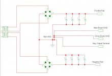
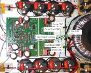
I attached a photo of the ground connections. All the grounds are soldered onto a copper wire that runs from the negative rail caps all the way to the positive rail caps, and has a sort of little loop right in the middle where all the GNDs are connected.
I had thought of what you suggest Stuart, but the caps I am using have tabs, so it would have been hard to solder them well onto a metal plate. The choices were to either use a homemade PCB, or use wire.
Paul
Attachments
How about taking a feed from the middle of the 3rd and 4th Caps to the star ground instead of taking it from the ends on the bank (i.e. first cap)
Hi Joey
Well, I would plug it in, fire it up, and see if you have anything to worry about first!
If you do, this is what I would do:
Drill a hole in the bottom of the chassis where your star ground is now. Crimp on eyelet connectors on to all your wires. Stick an M4, (or whatever your local equivalent) machine screw through and using locking nuts and star washers attach your mains input ground to it. Once tight, put some nut locking compound on so it never moves again. Put your connections on in this order, with star washers in between, PSU grounds, bridge grounds, speaker grounds, driver board ground, main board power ground, main board signal ground.
Does that make sense?
- Home
- Amplifiers
- Solid State
- Krell KSA 50 PCB